Mach-Lee
Well-Known Member
- First Name
- Lee
- Joined
- Jul 16, 2021
- Threads
- 262
- Messages
- 11,344
- Reaction score
- 24,963
- Location
- Wisconsin
- Vehicles
- 2022 Mach-E Premium AWD
- Occupation
- Sci/Eng
- Thread starter
- #1
I was asked to make a post about the changes made to the thermal systems in 2023.5 models and later. They include:
Base AWD:

It is now a single system with one coolant bottle (4). Larger PTC heater is shown (11). The key addition was a pair of 5-port valves (15 and 23) that allows coolant to flow to many destinations. The left 5-port (23) is focused on motor electronics cooling and battery heating/cooling. The right 5-port (15) is focused on cabin heating and coolant chilling. There are three loops within the system that can be combined or separated by the 5-port valves. These loops are the high voltage battery circuit, cabin heater circuit, and a powertrain electronics circuit.
A huge improvement here is the utilization of waste heat generated by the motor electronics and charger. On first-generation Mach-E's, the waste heat from AC charging and the motors/inverters can only be dissipated to the radiator. This heat is effectively lost to the surroundings. The new design allows the charger/motor waste heat to be sent to the battery pack instead of the radiator. This can provide a huge improvement to battery temperatures in winter conditions, and also opens up the possibility of heating the battery pack with the motors instead of the PTC heater for additional output (like Tesla and Rivian do). This should also increase the efficiency of the vehicle in cold conditions.
In the old design, 10% of the energy you use for charging is completely wasted. If you AC charge all night, the motors and radiator will be warm. This heat will quickly dissipate to the surroundings while driving. With the new design, this 10% of energy can be used to warm up the battery pack for free. Therefore in the morning you will have a warm battery pack, which means more range and less energy used for departure time preconditioning.
GT:
The GT functions similar to the base AWD, but with one additional cooling pump (21) added for the larger front motor.
RWD:
RWD is extremely similar to base AWD, just without the branch in the loop for the front motor.
Old Coolant Systems for comparison
5-port Coolant Diverter Valve:

The electrified powertrain cooling system use 5-port valves that have the capability to regulate, switch, mix or split coolant flow output to components of the system as needed for desired cooling or heating. The desired coolant flow is controlled by the SOBDM , SOBDMC , SOBDMB and PCM calibration as determined by input from the temperature sensors of the components within the electrified drivetrain cooling system. These components include:
7 kW PTC Cabin Heater (LFP only):

The heater is thicker than before.

The positive temperature coefficient (PTC) cabin heater has been increased in size from 5 kW to 7 kW on LFP pack models, providing 40% more heat output. The previous 5 kW models ran out of heat around 0ºF (-18ºC), the larger heater should hopefully allow the Mach-E to have heat down to -28ºF (-33ºC). It will also speed up battery heating times as well.
Note: 7 kW is the nominal heat output while cabin heating. PTC heaters can output more than nominal power in some situations, such as during battery heating with colder return temps (perhaps 8 kW). The output may briefly peak above 10 kW when first cycled on. But this is still considered a 7 kW nominal heater.
And before someone asks, I don't think the new heater can be retrofitted. It's physically larger and may not fit in old plumbing design. There will likely be issues with software control as well.
- PTC heater was upgraded from 5 kW to 7 kW on models with LFP pack (nominal continuous output, peak output may be slightly higher in some situations)
- New LFP pack is more sensitive to cold temps and requires more heating than NCM
- Glycol cooling is now a single system with three combined circuits rather than two separate systems (single coolant bottle instead of two coolant bottles)
- Addition of two 5-port valves allow excess heat to be utilized for battery heating (rather than being wasted)
- Removal of one coolant pump on base AWD models
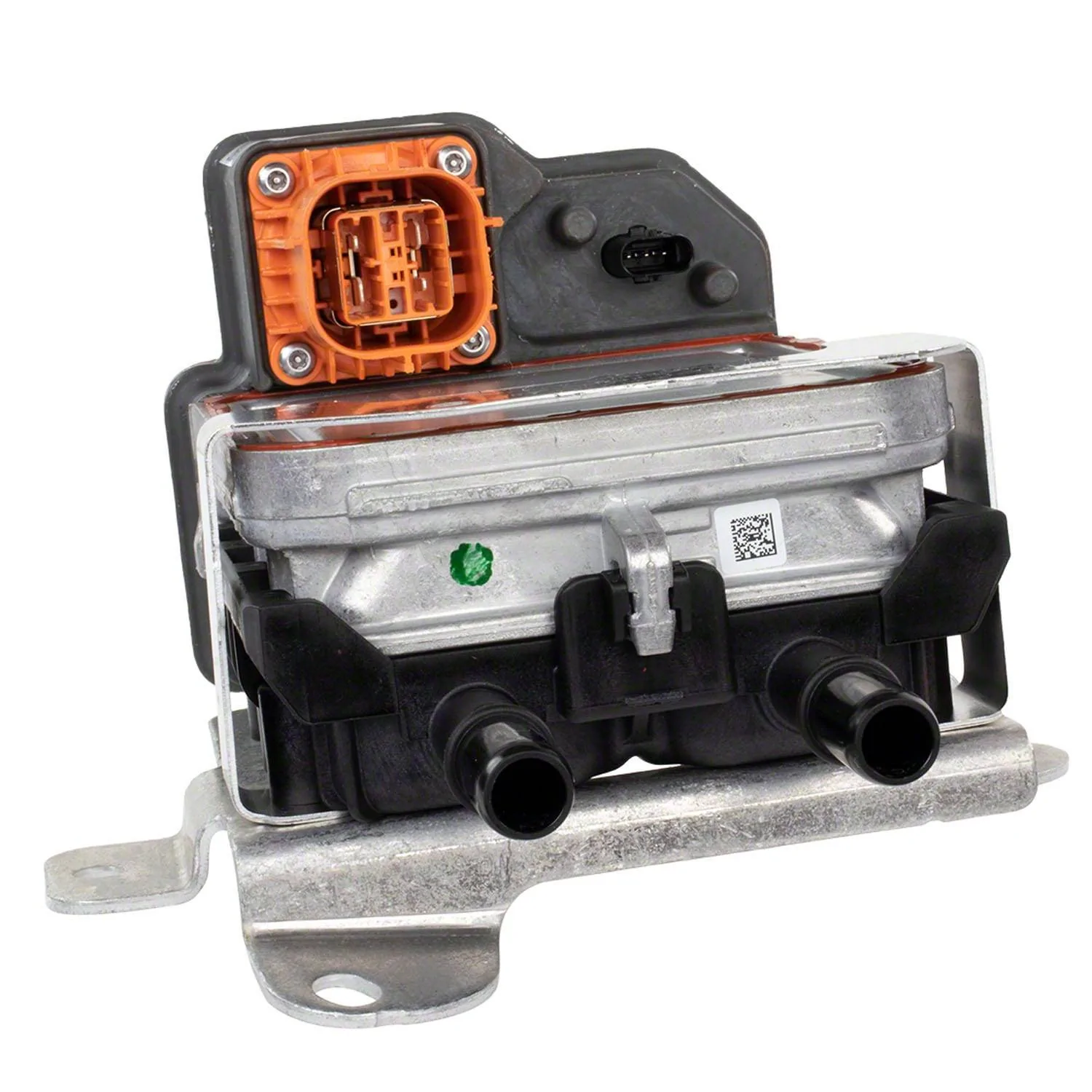
- New on-board AC charger from a different supplier, has different hookup locations
Base AWD:
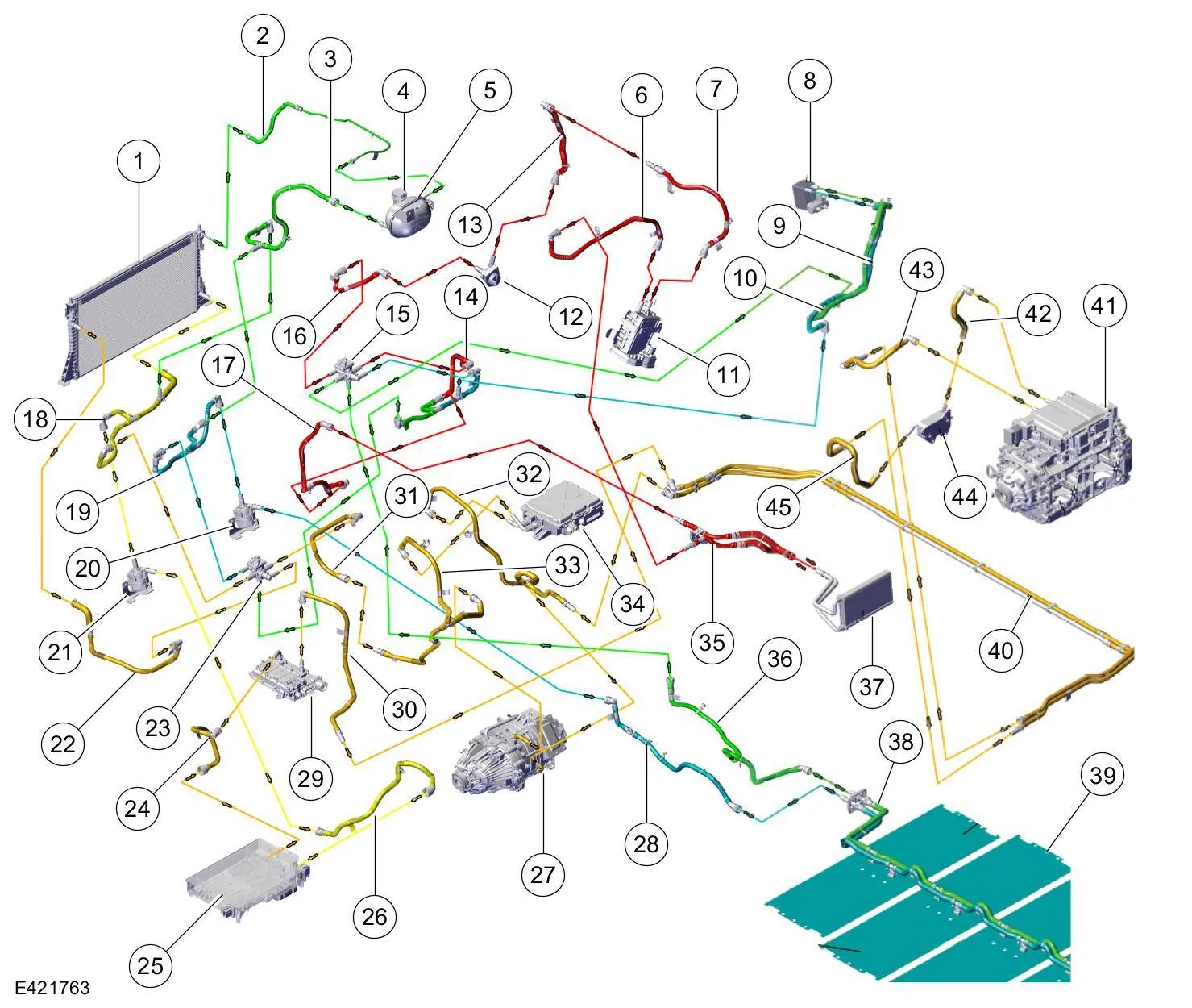
1 — Radiator
2 — Radiator vent hose
3 — Degas bottle lower hose
4 — Degas bottle cap
5 — Degas bottle
6 — Cabin coolant heater outlet hose
7 — Cabin coolant heater inlet hose
8 — High voltage battery coolant cooler
9 — High voltage battery coolant cooler inlet hose
10 — High voltage battery coolant cooler outlet hose
11 — Cabin coolant heater
12 — Cabin heater coolant pump
13 — Cabin heater coolant pump outlet hose
14 — High voltage battery coolant diverter valve inlet hose
15 — High voltage battery coolant diverter valve
16 — Cabin heater coolant pump inlet hose
17 — Heater core outlet hose
18 — Radiator lower hose
19 — High voltage battery coolant pump inlet hose
20 — High voltage battery coolant pump
21 — Motor electronics coolant pump
22 — Radiator upper hose
23 — High voltage battery radiator coolant diverter valve
24 — DC/DC inlet hose
25 — SOBDM (Secondary On-Board Diagnostic Control Module A)
26 — SOBDM inlet hose
27 — Front electric drive assembly
28 — High voltage battery coolant inlet hose
29 — DC/DC (Direct Current/Direct Current converter control module)
30 — DC/DC outlet hose
31 — High voltage battery radiator coolant diverter valve inlet hose
32 — Secondary inverter system controller [SOBDMB] inlet hose
33 — Secondary inverter system controller [SOBDMB] outlet hose
34 — Secondary inverter system controller [SOBDMB (Secondary On-Board Diagnostic Control Module B)]
35 — Heater core hose assembly
36 — High voltage battery coolant outlet hose
37 — Heater core
38 — High voltage battery coolant hose assembly
39 — High voltage battery plates
40 — Rear electric drive assembly lower coolant hose assembly
41 — Inverter system controller [SOBDMC (Secondary On-Board Diagnostic Control Module C)]
42 — Inverter system controller [SOBDMC] outlet hose
43 — Inverter system controller [SOBDMC] inlet hose
44 — Rear electric drive assembly oil cooler
45 — Rear electric drive assembly oil cooler outlet hose
Note: I figured these out, not Ford. There may be errors.
Cabin heat: 11, 6, 35, 37, 35, 17, 14, 15, 16, 12, 13, 7
Motor/Electronics cooling: 1, 18, 21, 26, 25, 24, 29, 30, 40, 43, 41, 42, 44, 45, 40, 32 [(34, 33),(27, 33)], 23, 22
Battery heat: 11, 6, 35, 37, 14, 23, 19, 20, 28, 38, 39, 38, 36, 15, 16, 12, 13, 7
Battery cool: 8, 9, 14, 23, 19, 20, 28, 38, 39, 38, 36, 15, 10
Waste heat to battery: 25, 24, 29, 30, 40, 43, 41, 42, 44, 45, 40, 32 [(34, 33),(27, 33)], 23, 19, 20, 28, 38, 39, 38, 36, 15, 14, 23, 18, 21, 26
Waste heat to battery + cabin: 25, 24, 29, 30, 40, 43, 41, 42, 44, 45, 40, 32 [(34, 33),(27, 33)], 23, 19, 20, 28, 38, 39, 38, 36, 15, 16, 12, 13, 7, 11, 6, 35, 37, 35, 17, 14, 23, 18, 21, 26
Cabin heat, Battery cool, and Motor/Electronics cooling should be able to operate simultaneously and independently of each other since they have their own pumps. Such as while DC charging.
It is now a single system with one coolant bottle (4). Larger PTC heater is shown (11). The key addition was a pair of 5-port valves (15 and 23) that allows coolant to flow to many destinations. The left 5-port (23) is focused on motor electronics cooling and battery heating/cooling. The right 5-port (15) is focused on cabin heating and coolant chilling. There are three loops within the system that can be combined or separated by the 5-port valves. These loops are the high voltage battery circuit, cabin heater circuit, and a powertrain electronics circuit.
A huge improvement here is the utilization of waste heat generated by the motor electronics and charger. On first-generation Mach-E's, the waste heat from AC charging and the motors/inverters can only be dissipated to the radiator. This heat is effectively lost to the surroundings. The new design allows the charger/motor waste heat to be sent to the battery pack instead of the radiator. This can provide a huge improvement to battery temperatures in winter conditions, and also opens up the possibility of heating the battery pack with the motors instead of the PTC heater for additional output (like Tesla and Rivian do). This should also increase the efficiency of the vehicle in cold conditions.
In the old design, 10% of the energy you use for charging is completely wasted. If you AC charge all night, the motors and radiator will be warm. This heat will quickly dissipate to the surroundings while driving. With the new design, this 10% of energy can be used to warm up the battery pack for free. Therefore in the morning you will have a warm battery pack, which means more range and less energy used for departure time preconditioning.
GT:
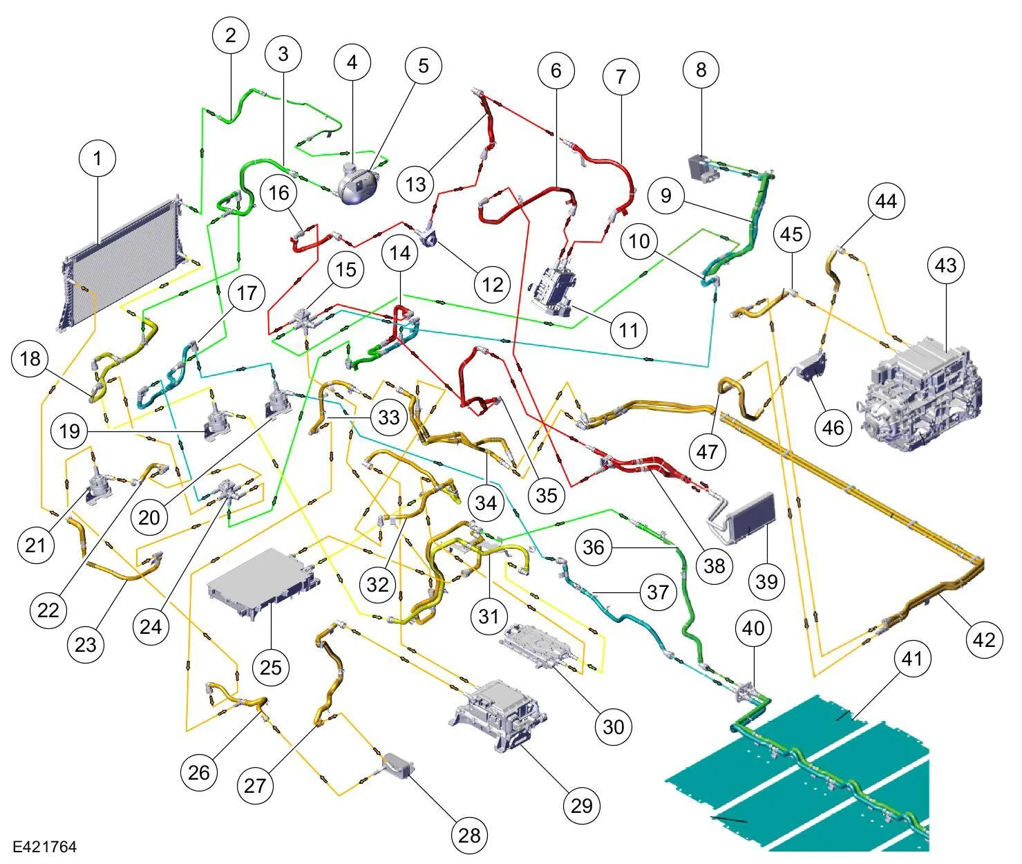
1 — Radiator
2 — Radiator vent hose
3 — Degas bottle lower hose
4 — Degas bottle cap
5 — Degas bottle
6 — Cabin coolant heater outlet hose
7 — Cabin coolant heater inlet hose
8 — High voltage battery coolant cooler
9 — High voltage battery coolant cooler inlet hose
10 — High voltage battery coolant cooler outlet hose
11 — Cabin coolant heater
12 — Cabin heater coolant pump
13 — Cabin heater coolant pump outlet hose
14 — High voltage battery coolant diverter valve inlet hose
15 — High voltage battery coolant diverter valve
16 — Cabin heater coolant pump inlet hose
17 — High voltage battery coolant pump inlet hose
18 — Radiator lower hose
19 — Motor electronics coolant pump
20 — High voltage battery coolant pump
21 — Motor electronics coolant pump - GT
22 — Motor electronics coolant pump - GT outlet hose
23 — Radiator upper hose
24 — High voltage battery radiator coolant diverter valve
25 — SOBDM (Secondary On-Board Diagnostic Control Module A)
26 — Front electric drive assembly oil cooler outlet hose
27 — Front electric drive assembly oil cooler inlet hose
28 — Front electric drive assembly oil cooler
29 — Secondary inverter system controller [SOBDMB (Secondary On-Board Diagnostic Control Module B)]
30 — DC/DC (Direct Current/Direct Current converter control module)
31 — DC/DC inlet hose
32 — Secondary inverter system controller [SOBDMB] inlet hose
33 — Rear electric drive assembly coolant outlet hose
34 — Rear electric drive assembly coolant hose assembly
35 — Heater core outlet hose
36 — High voltage battery coolant outlet hose
37 — High voltage battery coolant inlet hose
38 — Heater core hose assembly
39 — Heater core
40 — High voltage battery coolant hose assembly
41 — High voltage battery plates
42 — Rear electric drive assembly lower coolant hose assembly
43 — Inverter system controller [SOBDMC (Secondary On-Board Diagnostic Control Module C)]
44 — Inverter system controller [SOBDMC] outlet hose
45 — Inverter system controller [SOBDMC] inlet hose
46 — Rear electric drive assembly oil cooler
47 — Rear electric drive assembly oil cooler outlet hose
The GT functions similar to the base AWD, but with one additional cooling pump (21) added for the larger front motor.
RWD:
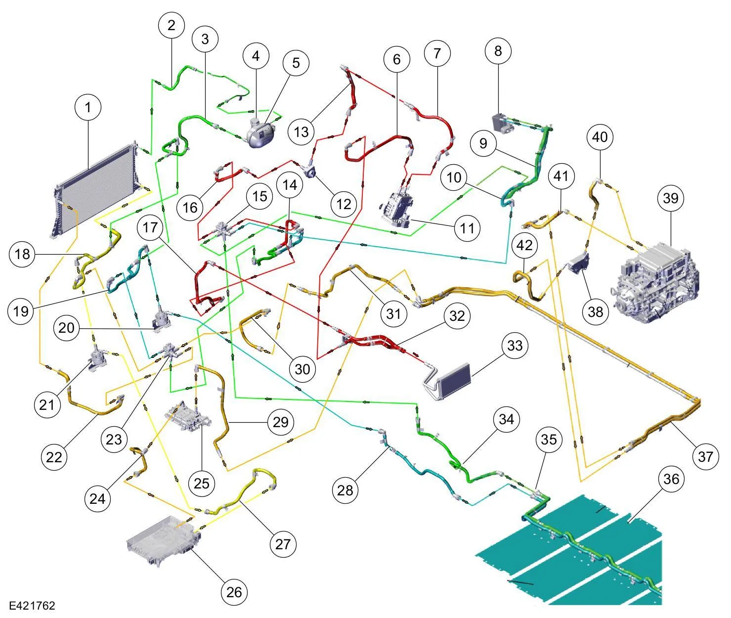
1 — Radiator
2 — Radiator vent hose
3 — Degas bottle lower hose
4 — Degas bottle cap
5 — Degas bottle
6 — Cabin coolant heater outlet hose
7 — Cabin coolant heater inlet hose
8 — High voltage battery coolant cooler
9 — High voltage battery coolant cooler inlet hose
10 — High voltage battery coolant cooler outlet hose
11 — Cabin coolant heater
12 — Cabin heater coolant pump
13 — Cabin heater coolant pump outlet hose
14 — High voltage battery coolant diverter valve inlet hose
15 — High voltage battery coolant diverter valve
16 — Cabin heater coolant pump inlet hose
17 — Heater core outlet hose
18 — Radiator lower hose
19 — High voltage battery coolant pump inlet hose
20 — High voltage battery coolant pump
21 — Motor electronics coolant pump
22 — Radiator upper hose
23 — High voltage battery radiator coolant diverter valve
24 — DC/DC inlet hose
25 — DC/DC (Direct Current/Direct Current converter control module)
26 — SOBDM (Secondary On-Board Diagnostic Control Module A)
27 — SOBDM inlet hose
28 — High voltage battery coolant inlet hose
29 — DC/DC outlet hose
30 — High voltage battery radiator coolant diverter valve inlet hose
31 — Rear electric drive assembly coolant outlet hose
32 — Heater core hose assembly
33 — Heater core
34 — High voltage battery coolant outlet hose
35 — High voltage battery coolant hose assembly
36 — High voltage battery plates
37 — Rear electric drive assembly lower coolant hose assembly
38 — Rear electric drive assembly oil cooler
39 — Inverter system controller [SOBDMC (Secondary On-Board Diagnostic Control Module C)]
40 — Inverter system controller [SOBDMC] outlet hose
41 — Inverter system controller [SOBDMC] inlet hose
42 — Rear electric drive assembly oil cooler outlet hose
RWD is extremely similar to base AWD, just without the branch in the loop for the front motor.
Old Coolant Systems for comparison
5-port Coolant Diverter Valve:
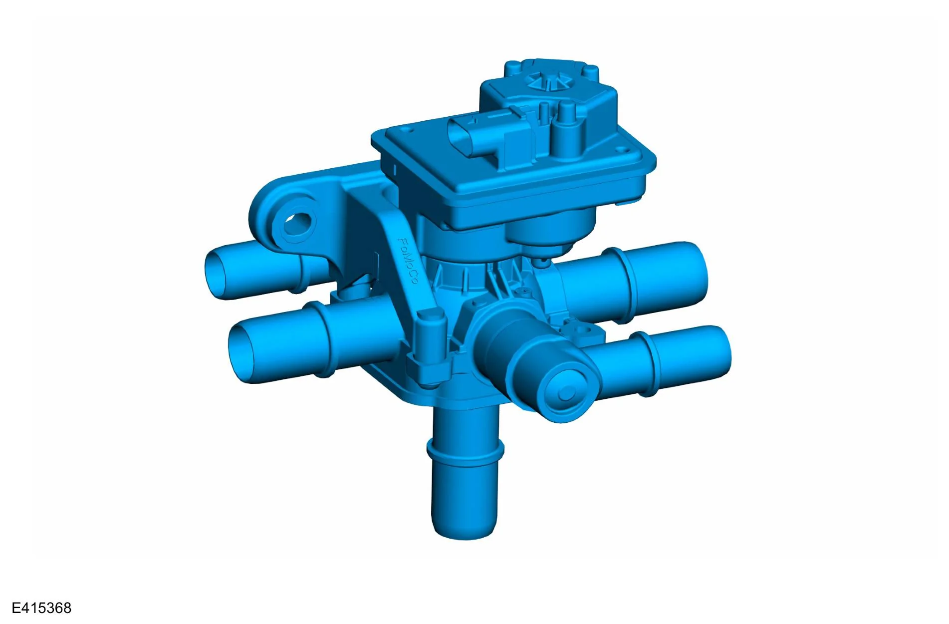
The electrified powertrain cooling system use 5-port valves that have the capability to regulate, switch, mix or split coolant flow output to components of the system as needed for desired cooling or heating. The desired coolant flow is controlled by the SOBDM , SOBDMC , SOBDMB and PCM calibration as determined by input from the temperature sensors of the components within the electrified drivetrain cooling system. These components include:
- Electric drive assemblies
- High voltage battery
- SOBDM
- SOBDMC
- SOBDMB
- DCDC
- Cabin heater coolant pump
7 kW PTC Cabin Heater (LFP only):
The heater is thicker than before.
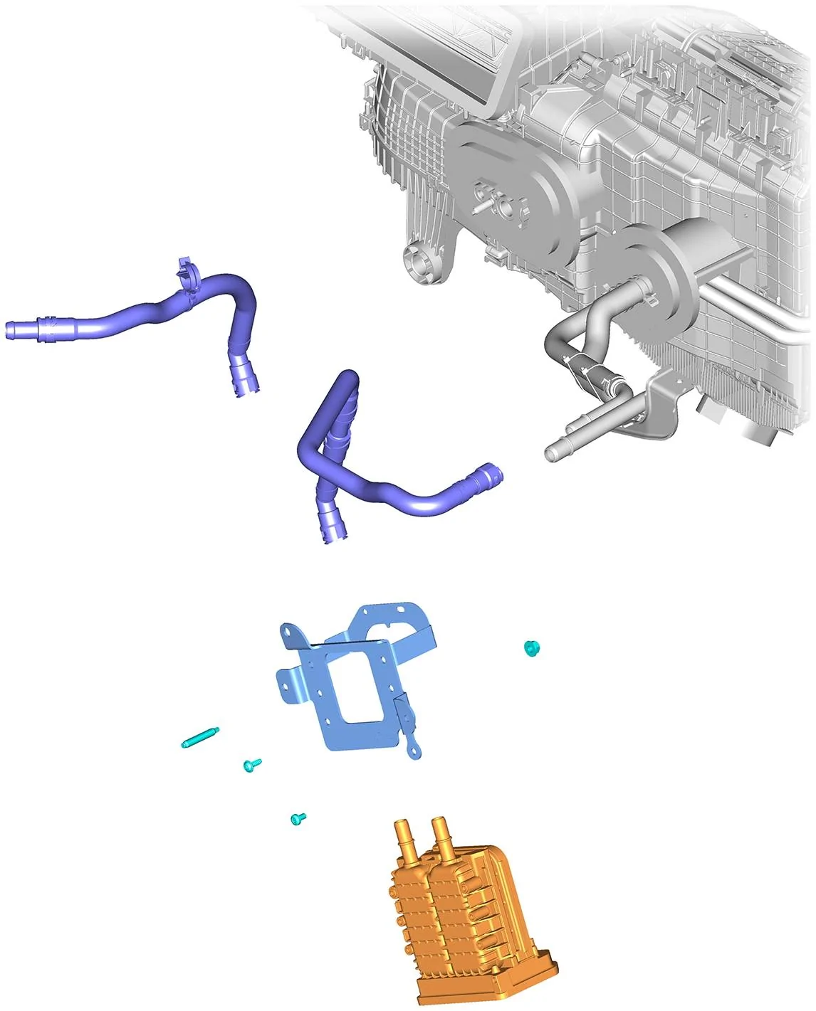
The positive temperature coefficient (PTC) cabin heater has been increased in size from 5 kW to 7 kW on LFP pack models, providing 40% more heat output. The previous 5 kW models ran out of heat around 0ºF (-18ºC), the larger heater should hopefully allow the Mach-E to have heat down to -28ºF (-33ºC). It will also speed up battery heating times as well.
Note: 7 kW is the nominal heat output while cabin heating. PTC heaters can output more than nominal power in some situations, such as during battery heating with colder return temps (perhaps 8 kW). The output may briefly peak above 10 kW when first cycled on. But this is still considered a 7 kW nominal heater.
And before someone asks, I don't think the new heater can be retrofitted. It's physically larger and may not fit in old plumbing design. There will likely be issues with software control as well.
Sponsored
Last edited: