Mach-Lee
Well-Known Member
- First Name
- Lee
- Joined
- Jul 16, 2021
- Threads
- 262
- Messages
- 11,365
- Reaction score
- 25,025
- Location
- Wisconsin
- Vehicles
- 2022 Mach-E Premium AWD
- Occupation
- Sci/Eng
- Thread starter
- #1
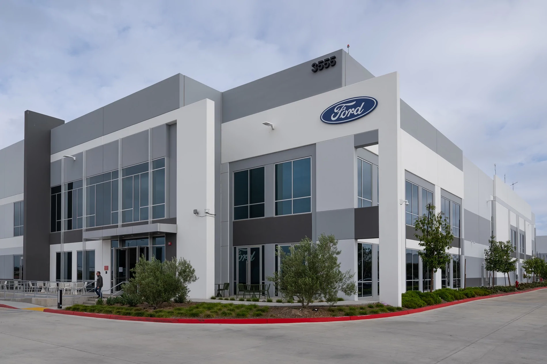
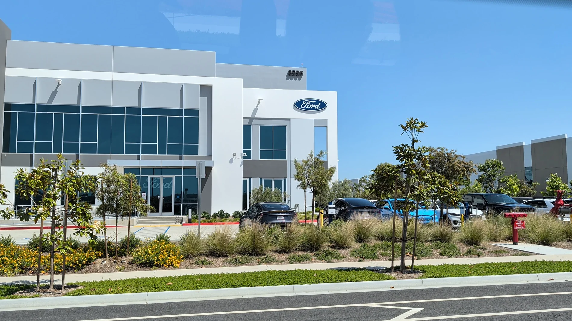
Last week Ford held an event at their Electric Vehicle Development Center (EVDC) in Long Beach, CA. You’ll hear from a few regulars here, we were able to tour their new facilities that are busy developing the new Universal Electric Vehicle (UEV) platform. The current work is focused on finalizing the design of the new midsize electric truck.

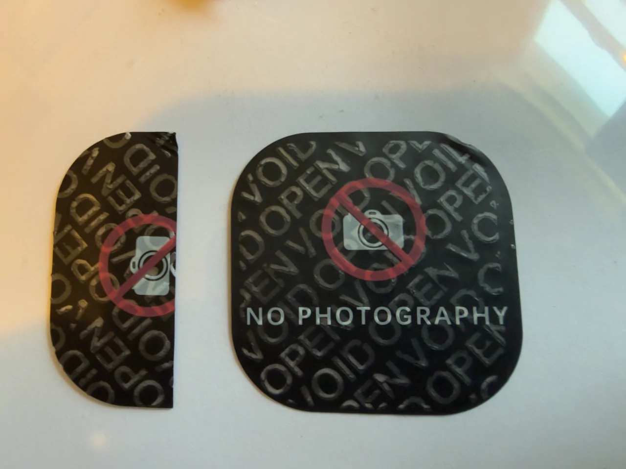
The tour was focused on the facilities rather than the vehicle itself, although we “happened” to catch a brief glimpse of a camouflaged test mule truck near the end. More on that later. We were not allowed to take photos during the tour, but Ford gave us unprecedented access to their facility, colloquially known as the “Skunkworks”.
The tour began with opening remarks from Alan Clarke, the director of the EVDC. He spoke about adapting Kelly Johnson’s 14 rules of running a Skunk Works which famously designed the U-2, SR-71, and F-117 stealth aircraft for the EVDC.
I will describe what I saw chronologically. This will be a long post, but that’s my style.
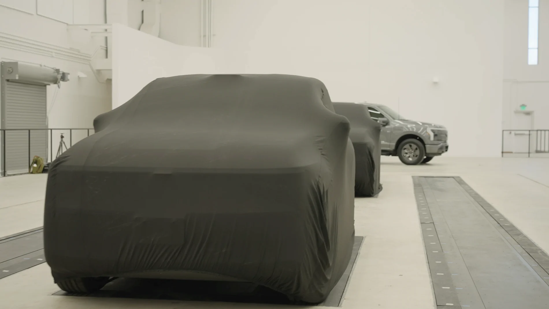
Design Studio
Overall, it was a very nice, brand-new facility inside. On our way in, we saw a few employees “coding” at workstations. The first “stop” was the design studio, where we saw a front unicasting, structural battery pack with seats, and a firewall-back body-in-white (rear was covered). Ford’s goal is to build the vehicle in a completely different way that minimizes components, wasted assembly line space, and production time. In order to build the vehicle differently, it has to be designed differently from the start. The legacy way is to weld the body together first, then put all the interior components and trim in through the door openings. The new way is to do as much of the assembly in parallel as possible, then put together big, almost fully complete pieces. A good example of this are firewall components, such as the blower housing and the accelerator and brake pedals. These can now be easily installed on the front casting subassembly before it’s mated to the rest of the car. Same with the seats, they can be bolted on top of the battery pack rather than having to go in through the door openings. This also is far more ergonomic for assembly workers.
Adjacent was a gigantic open room for clay model design (complete with a vehicle turntable). Yes, they still sculpt shapes out of clay to get them just right. There were large tracks in the floor for laser scanning machines, they also had a CNC milling machine to sculpt shapes into clay. Basically, they can go both directions with shapes—clay to computer, and computer to clay.
We were also teased by several covered prototype models of the midsize truck in this room.

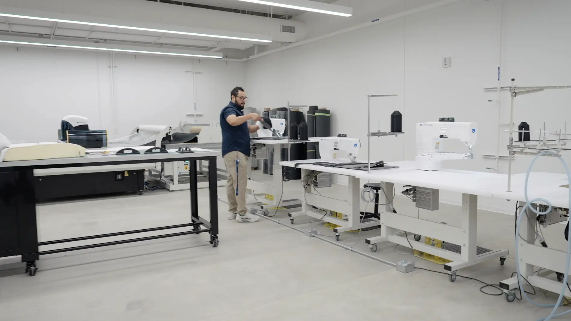
Trim shop
Next stop was the trim shop where they make seats. We saw a large pattern cutter, sewing machines, pattern making software, and prototype seat covers. With this shop, Ford can rapidly prototype various seat profiles and cover variations in only a week, rather than a 3+ month process with an outside supplier. There was a focus on eliminating material waste by optimizing pattern cutting with computer software. A small change in a seat shape can sometimes make a large difference in scrap waste if the pieces can be packed more closely together on the pattern cutter.
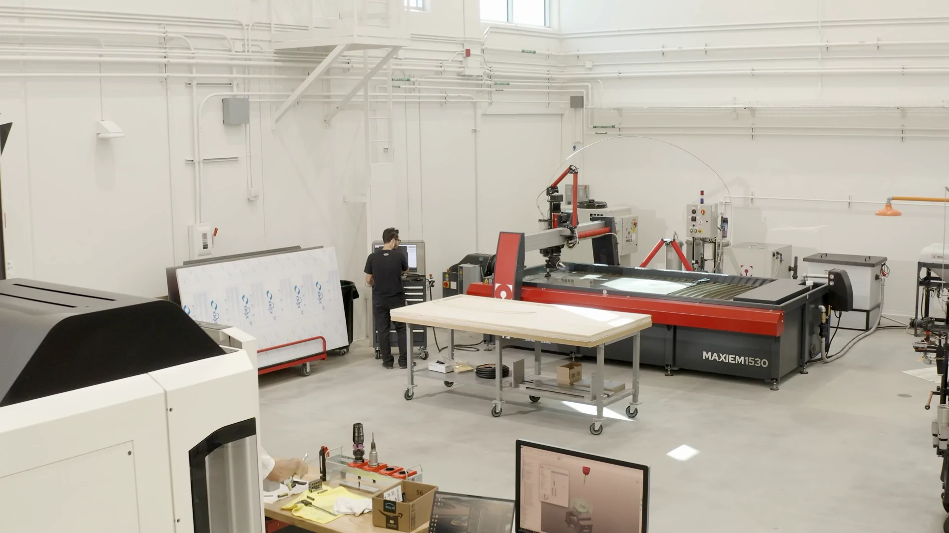
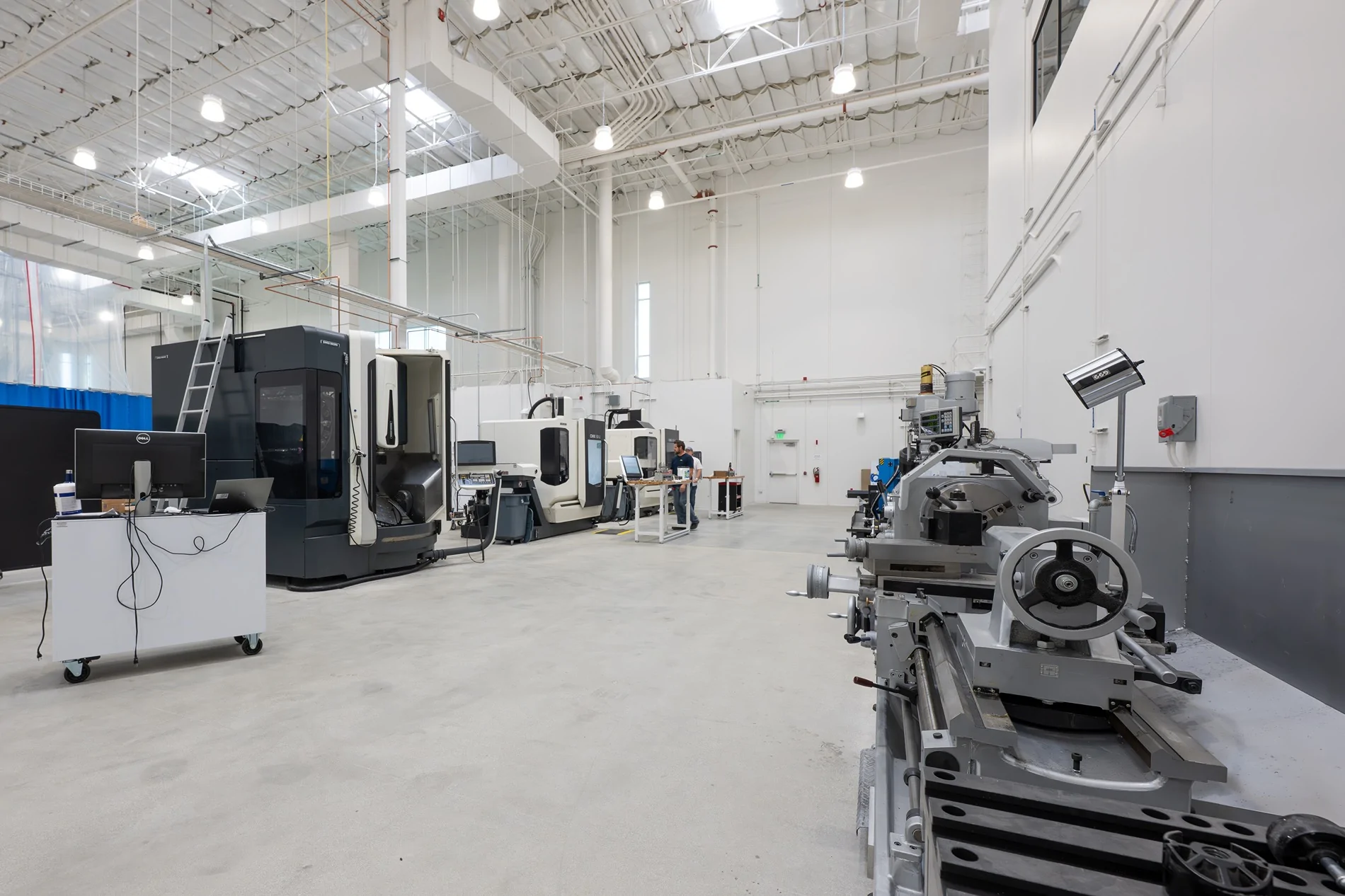
Fabrication Shop
Down the hall in the fabrication shop, the centerpiece was a huge foam milling machine. They said it had the ability to make any size and shape part out of pink foam, from a small switch all the way up to an entire foam vehicle for aerodynamic testing. Foam examples shown were an entire hood and a tailgate. They also had about a dozen Bambu Labs 3D printers, and a larger SLA machine. Not shown to us, but they also have a complete metalworking shop including a waterjet cutter, multiple CNC machines, press brake, and welding tables. The paint shop allows them to test any color combination or surface finish (matte, gloss) on interior or exterior parts. Basically, in this part of the budling they can rapidly make whatever shape and size material they need to for mockup and prototyping purposes.
To demonstrate the past, they had a plywood mockup of a generic prototype vehicle with real seats installed. This was the “old” method to test spacing, roominess, and sightlines. The new method involves the use of 3D foam cutting, painting, and fabricated metal parts to make mockups that are more accurate than ever before. Small design changes can be precisely iterated.
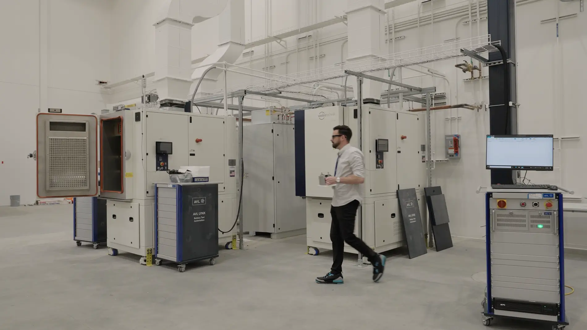
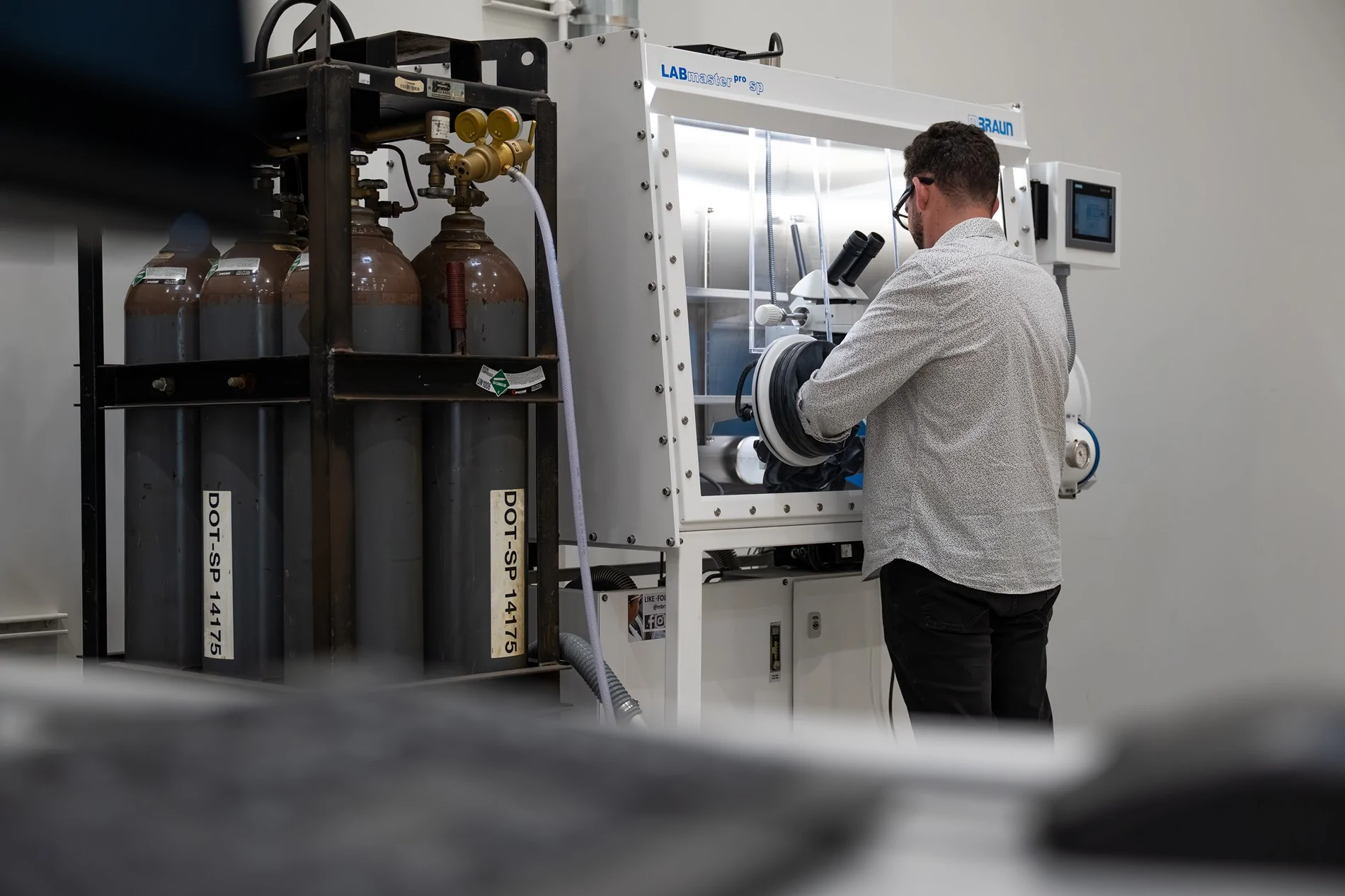
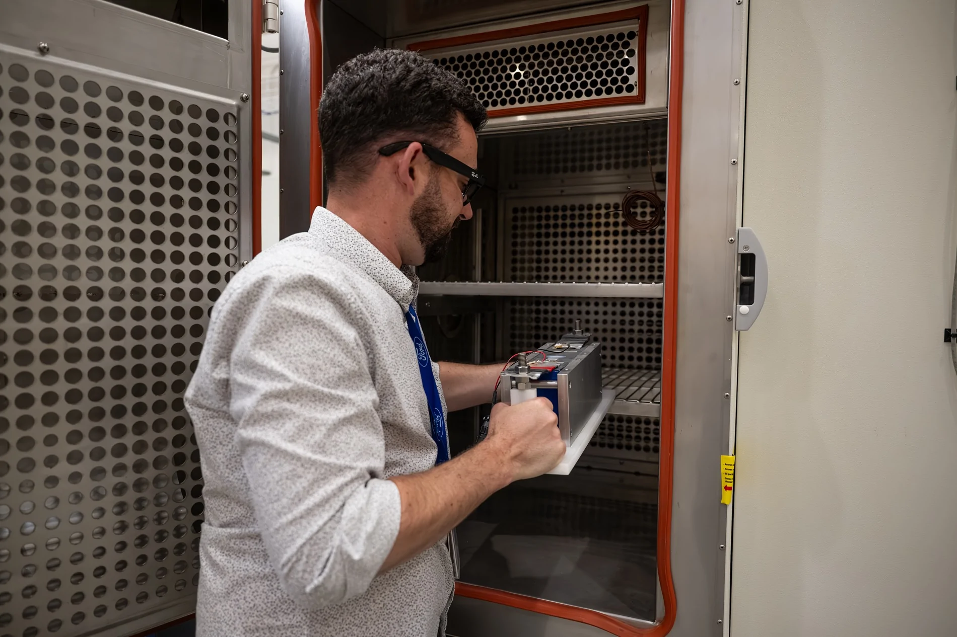
Battery Lab
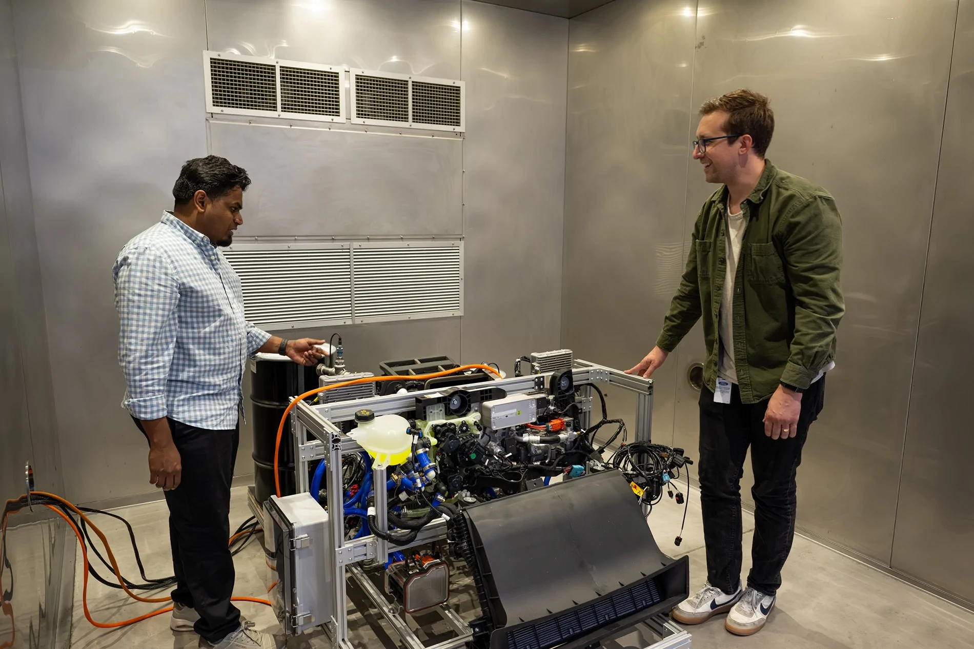
This area was still under development, but had several environmental chambers for battery cell testing. They also had a laser welder (for welding cell tabs), and a glove box (inert atmosphere) for dissembling cells. The centerpiece was a large overhead crane assembly, this would be used to lift cell modules and battery packs. They said this is where they can explore different battery pack assembly methods.
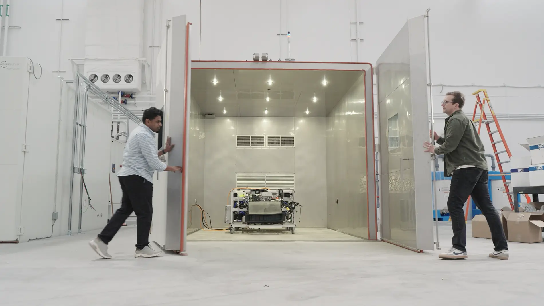
Thermal Lab
This area has several large environmental test chambers for testing the extremes of temperature on components. Some of the chambers was large enough to contain an entire battery pack or subassembly. One was large enough to contain an entire vehicle, and has solar lighting installed (to simulate the heat of the sun). They said they will test the vehicles in temps ranging from -40ºC to +60ºC.
The crown jewel here was a very large (small house size) environmental chamber being built around a rolling AWD dynamometer. The car sits in the center with wheels spinning on the rollers. This high-precision dynamometer is capable of simulating whatever speed and road load profiles they want. Other features are a gigantic fan for simulating wind, and there will be a full solar array installed near the ceiling of the chamber to simulate solar loads. There will also be a high-power DC fast charger installed immediately adjacent to recharge vehicles on the dyno, with high-fidelity energy monitoring. For example, they can simulate the road load of driving up a mountain on a hot day and then immediately DC fast charging to stress the vehicle thermal systems. This dyno will also be certified for EPA range testing (it will run the EPA test cycles, every Wh measured), so Ford can determine the MPGe and range that goes on the window sticker.
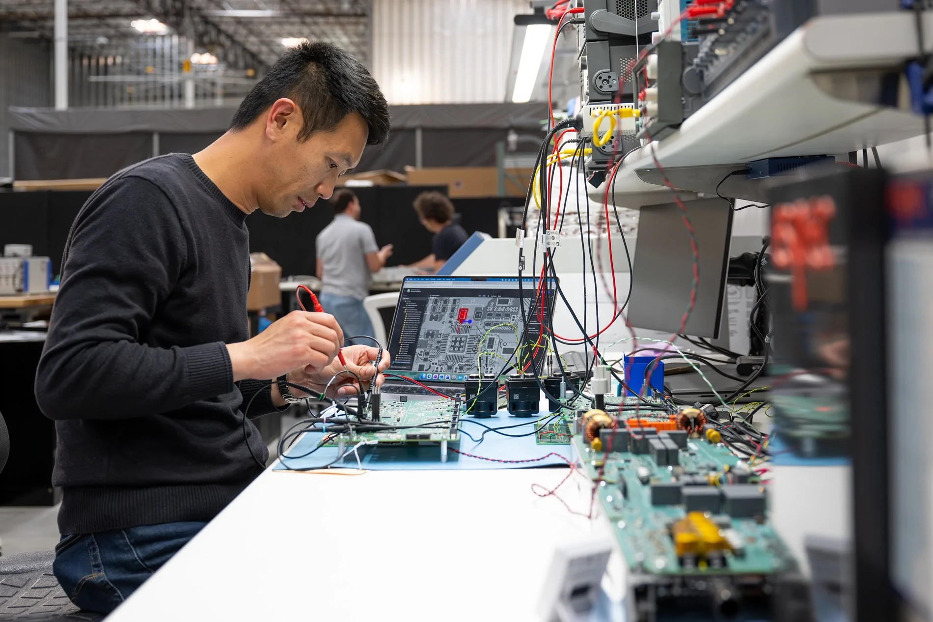
High Voltage and Electrical Lab
This lab was the most technologically advanced. There were racks of electronics equipment, wires going everywhere. Lots of test equipment and soldering stations for working on circuit boards. More environmental test chambers with battery cells inside. They were currently running an EPA discharge cycle on a test cell, monitoring voltage and current. On a table they had a few high voltage components out on display us, a motor inverter, the Ebox, and the charge port. The Ebox contains the high voltage contactors, as well as the on-board charger, DC/DC converter (48V output), and inverter for AC output/bidirectional charging. There are liquid cooling ports on the end of it for the power electronics, it’s essentially an extra-long HVBJB but overall much smaller than the size of the legacy parts it would replace. The charge port was very interesting—it’s a NACS port with a locking mechanism, but they have also integrated a local body module on the backside of it, a 2-in-1. There are wire harness connectors at the bottom back of it, these might be used to power nearby body components such as the charge port door and the taillights. Interesting design choice for sure.
There was a brief stop with a Faraday tent and dipole antenna for testing spurious RF emissions of electronics. Basically, they can make sure the power electronics are not going to cause interference to AM/FM radio, broadcast, or military radio frequencies.
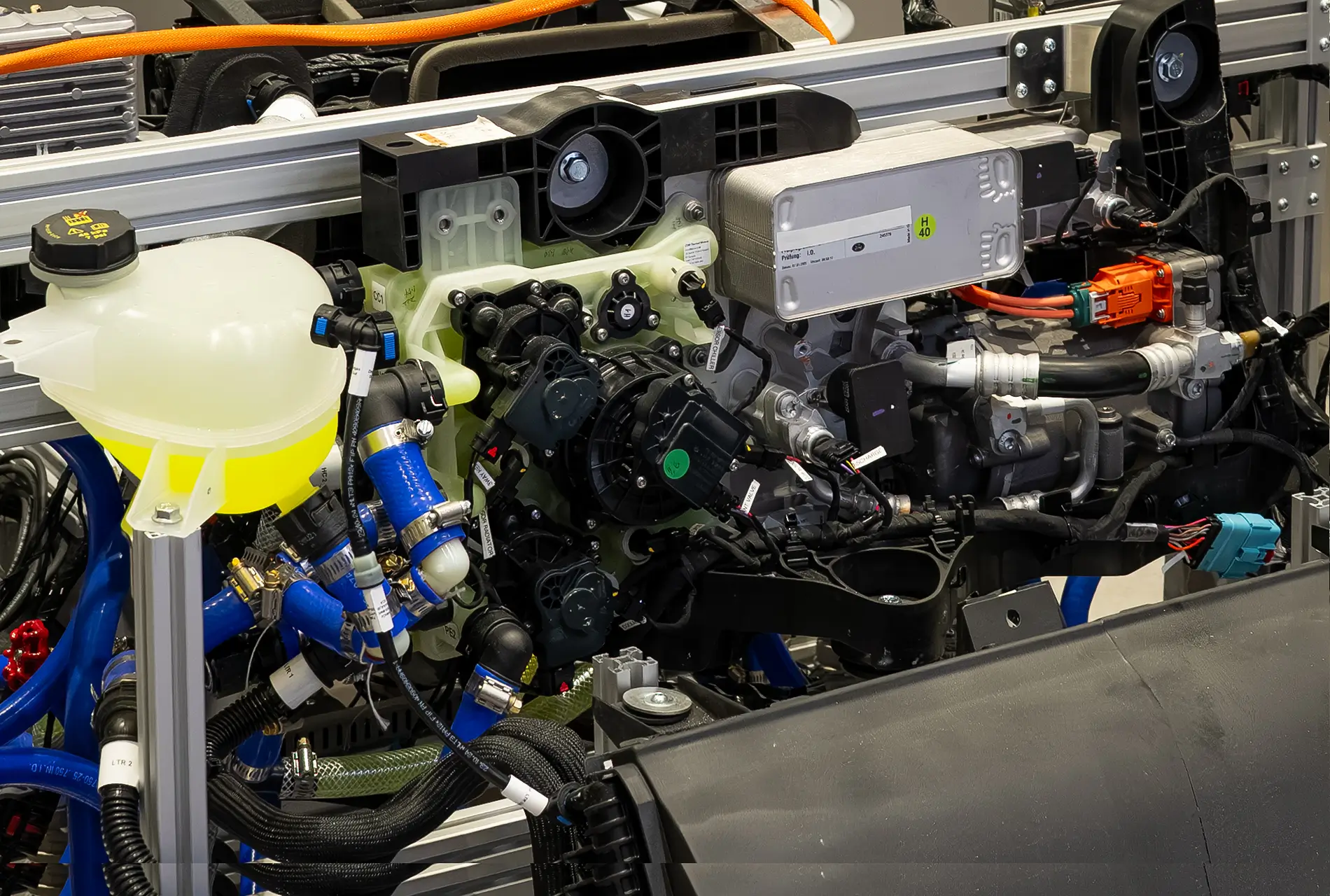
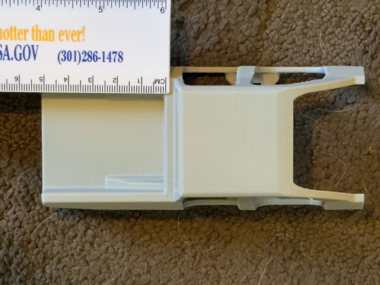
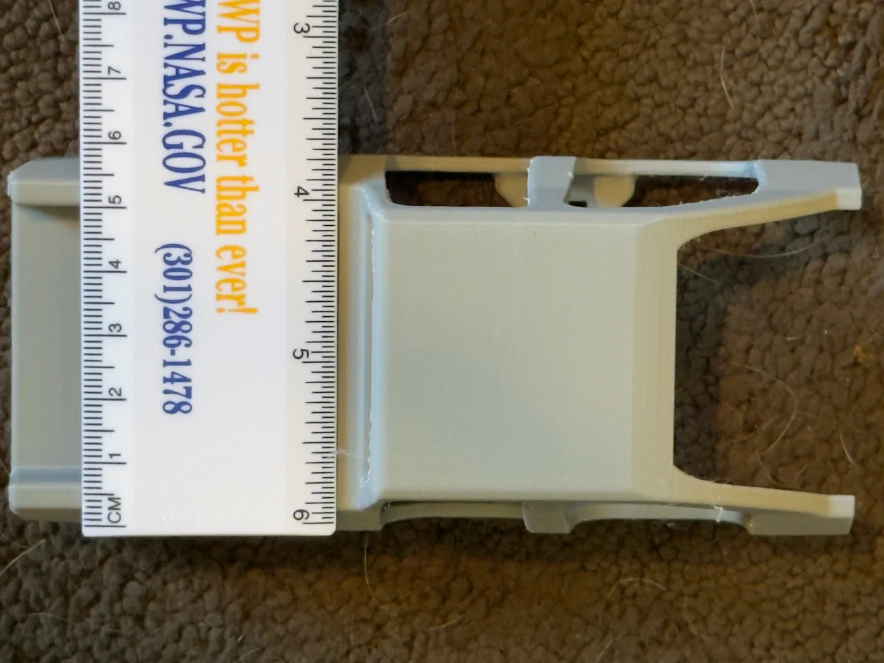
The next station was my favorite—it showed the new heat pump and thermal/HVAC system installed in the front unicasting. All the coolant hoses were hooked up for testing in an environmental chamber. The big news here is Ford has designed an integrated coolant manifold that is the size of a large textbook (contains several pumps and valves in one). This would be Ford’s equivalent of the Tesla Octovalve. This manifold is the consolidated solution to all the crazy coolant piping and pumps everywhere in the current generation Ford EVs. All the inputs/outputs are consolidated on the left side (looks like about four loop pairs), and the run to heater core is much more direct. There were two plate heat exchangers or chillers, I presume one for water-to-refrigerant and the other for water-to-water heat transfer. They said with this setup they can basically transfer heat to and from whatever components they need to (e.g. motor to cabin, charger to battery, etc.)
Closeup of new coolant manifold:

The compressor is mounted right next to the coolant manifold on the same frame, EEVs right there too. Another big new feature they announced is the heat pump is capable of vapor injection or hot gas bypass. This is a feature of cold weather heat pumps, and allows the heat pump to continue operating and essentially generate its own heat down to a colder ambient temperature. They said this will allow the elimination of the PTC heater, although the prototype still had a PTC heater installed. Hopefully this new thermal system is up to keeping the cabin and battery warm even in harsh Canadian arctic temps, while being more efficient.
The thermal system was packaged nicely along the firewall, this should allow there to be a small frunk space in front of it. Probably not much bigger than medium duffle bag, but that’s the tradeoff for having a heat pump.
Wiring Integration Lab
There were several body components from the truck connected together with wiring harnesses (headlights, taillights, window regulators, switches, steering wheel, touchscreen) on a test grid. This is used to test for any mistakes in a device’s pinout (such as swapped signal and ground pins) and to integrate all the modules together and make sure they talk to each other as expected. The electrical system is primarily 48VDC (which reduces wire size and cost), although there may still be some 12V components in places.
I saw some interesting things here. Speculation warning, none of this is confirmed. The center touchscreen was covered, but is horizontal. There was not a separate instrument cluster screen (but perhaps it had been removed). The steering wheel was there, and the buttons on it seem to be a new layout for Ford. Rather than defined buttons, there was a small scroll wheel on each side, and also a left and right arrow button on each side. Still had stalks on both sides as well. That’s about it. That would support the presence of a more software defined UI experience. The thumbwheels and screen remind me of a Tesla Model 3/Y (also sans instrument cluster?).
The NACS charge port was in the left rear of the vehicle layout.
The wiring mockup was being powered by a power supply installed in the location of the Ebox (backseat area). I did not see any low voltage battery in the setup. Nor did I see any provisions for one. The DC/DC is in the Ebox, so ideally the LVB would be located close by. Wonder if they figured out a way to eliminate a LVB, we’ll see.
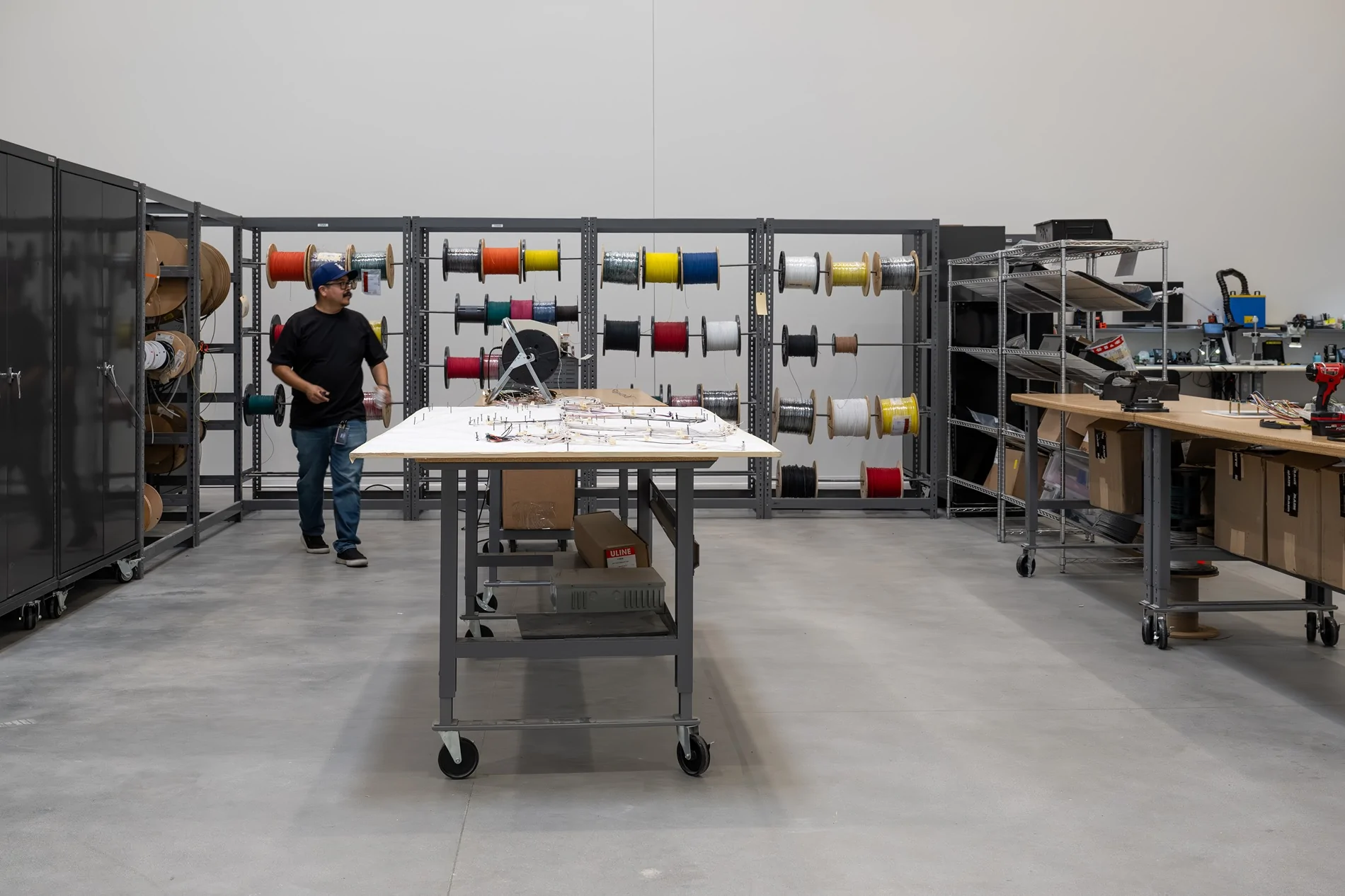
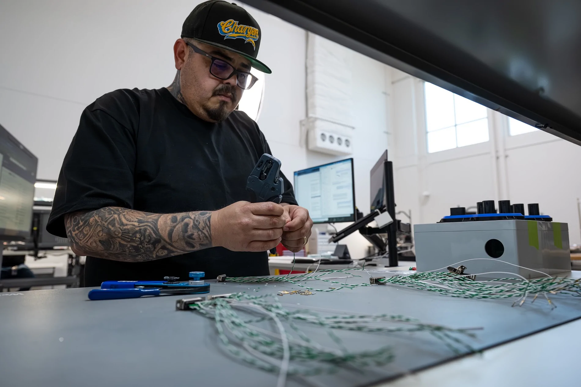
Harness Lab
Here they can build whatever wire harness they need, with whatever connectors they need. Pretty self-explanatory. Spools of wire, bins of connectors and pins, soldering/test station. They were building a harness on a board with nails for each intersection.
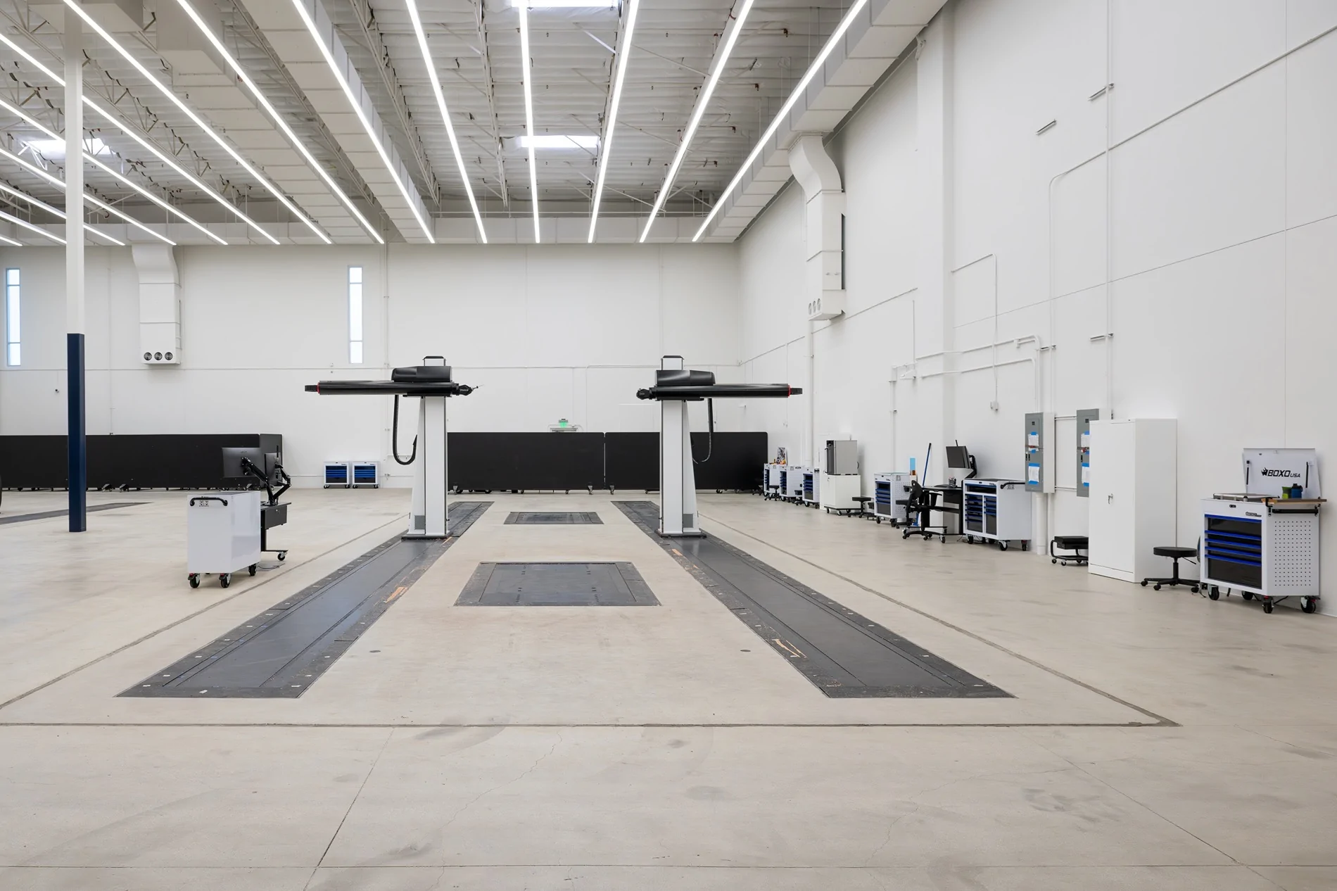
Metrology Lab
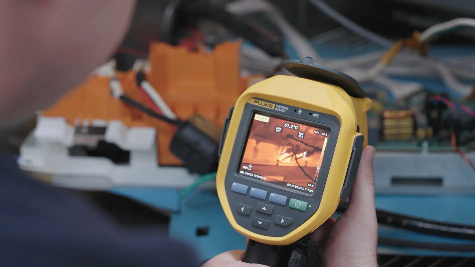
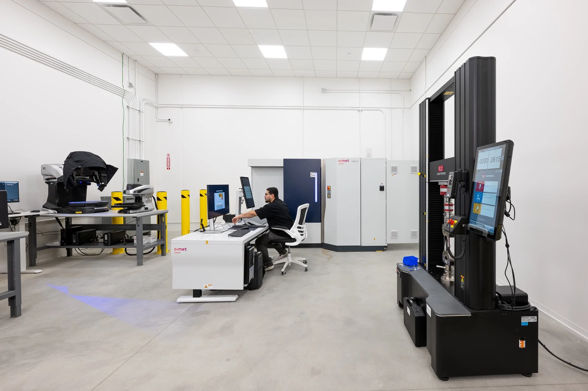
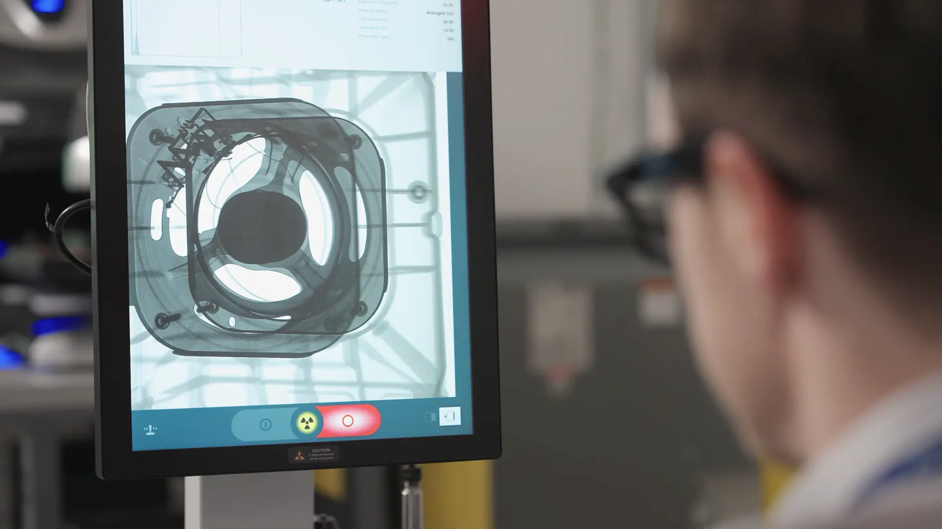
Metrology is the science of measurement. This lab has several machines for measuring dimensions and properties of materials. First shown was a handheld 3D laser scanner which can measure and verify part dimensions. A center console was scanned for a demo. They had a universal testing machine or tensile tester. They pulled a piece of metal plate apart with it to measure the stress-strain curve. They also had a large industrial CT scanner, which can see inside parts. This can be usual for finding voids or electrode defects, also for examining for cracked solder joints, among many uses. They also had a measuring microscope, turntable 3D scanner and a laser-induced breakdown spectrometry (LIBS) machine for determining elemental composition.
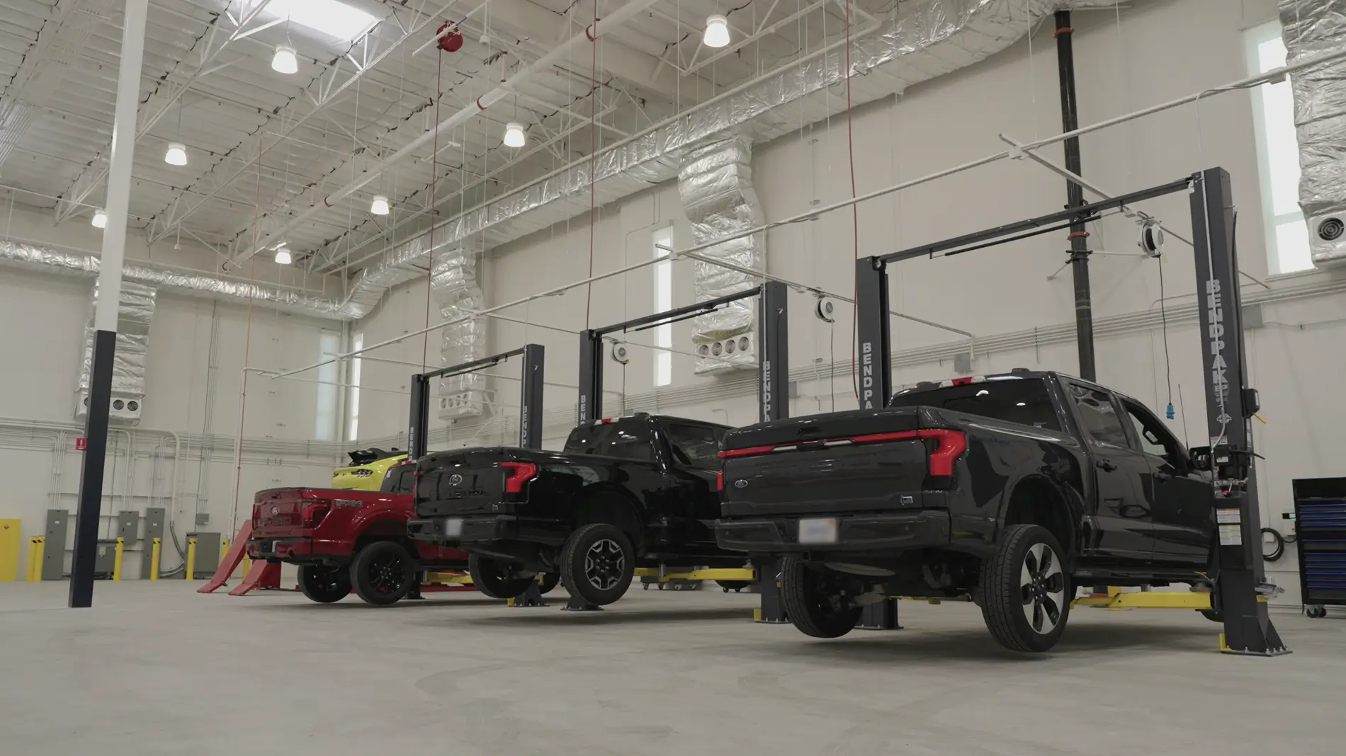
Fleet Center
Last was a large garage with about six two-post lifts. They said these are used to work on prototype vehicles and test mules. For example, they can raise or take apart vehicles to install extra instrumentation sensors. The technician recalled recently installing over 500 thermocouples at various places in the vehicle for real-world thermal testing.
Conclusion
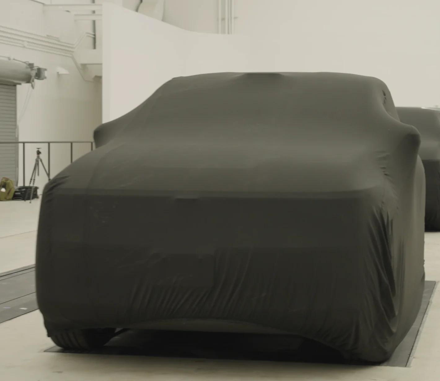
On our walk back to the entrance, we were surprised by a camouflaged test mule of the truck. To put some things in perspective, it looked bigger than a Maverick but smaller than a Ranger. Similar ground clearance, probably around 8”. The front looked more like a rounded SUV nose rather than the boxy truck (but not ugly). Roof had the distinctive curved down slope and the bed looked about the same length as the maverick (4.5’). They supposedly have stated test production and final validation with about 100 units scheduled. They still anticipate a mid 2027 release for the truck.
Overall, this was an impressive tour that showcased Ford’s investment in EVs and the future of the company. There were a lot of expensive machines here. But overall, the EVDC feels much like a smaller start-up engineering firm. I guess that’s the best of both worlds, small company vibe with the freedom to do things their way, but backed by the major capital of Ford. I liked what I saw, overall these guys should have the tools at their disposal to make a great EV.
The tour was focused on the facilities rather than the vehicle itself, although we “happened” to catch a brief glimpse of a camouflaged test mule truck near the end. More on that later. We were not allowed to take photos during the tour, but Ford gave us unprecedented access to their facility, colloquially known as the “Skunkworks”.
The tour began with opening remarks from Alan Clarke, the director of the EVDC. He spoke about adapting Kelly Johnson’s 14 rules of running a Skunk Works which famously designed the U-2, SR-71, and F-117 stealth aircraft for the EVDC.
I will describe what I saw chronologically. This will be a long post, but that’s my style.
Design Studio
Overall, it was a very nice, brand-new facility inside. On our way in, we saw a few employees “coding” at workstations. The first “stop” was the design studio, where we saw a front unicasting, structural battery pack with seats, and a firewall-back body-in-white (rear was covered). Ford’s goal is to build the vehicle in a completely different way that minimizes components, wasted assembly line space, and production time. In order to build the vehicle differently, it has to be designed differently from the start. The legacy way is to weld the body together first, then put all the interior components and trim in through the door openings. The new way is to do as much of the assembly in parallel as possible, then put together big, almost fully complete pieces. A good example of this are firewall components, such as the blower housing and the accelerator and brake pedals. These can now be easily installed on the front casting subassembly before it’s mated to the rest of the car. Same with the seats, they can be bolted on top of the battery pack rather than having to go in through the door openings. This also is far more ergonomic for assembly workers.
Adjacent was a gigantic open room for clay model design (complete with a vehicle turntable). Yes, they still sculpt shapes out of clay to get them just right. There were large tracks in the floor for laser scanning machines, they also had a CNC milling machine to sculpt shapes into clay. Basically, they can go both directions with shapes—clay to computer, and computer to clay.
We were also teased by several covered prototype models of the midsize truck in this room.
Trim shop
Next stop was the trim shop where they make seats. We saw a large pattern cutter, sewing machines, pattern making software, and prototype seat covers. With this shop, Ford can rapidly prototype various seat profiles and cover variations in only a week, rather than a 3+ month process with an outside supplier. There was a focus on eliminating material waste by optimizing pattern cutting with computer software. A small change in a seat shape can sometimes make a large difference in scrap waste if the pieces can be packed more closely together on the pattern cutter.
Fabrication Shop
Down the hall in the fabrication shop, the centerpiece was a huge foam milling machine. They said it had the ability to make any size and shape part out of pink foam, from a small switch all the way up to an entire foam vehicle for aerodynamic testing. Foam examples shown were an entire hood and a tailgate. They also had about a dozen Bambu Labs 3D printers, and a larger SLA machine. Not shown to us, but they also have a complete metalworking shop including a waterjet cutter, multiple CNC machines, press brake, and welding tables. The paint shop allows them to test any color combination or surface finish (matte, gloss) on interior or exterior parts. Basically, in this part of the budling they can rapidly make whatever shape and size material they need to for mockup and prototyping purposes.
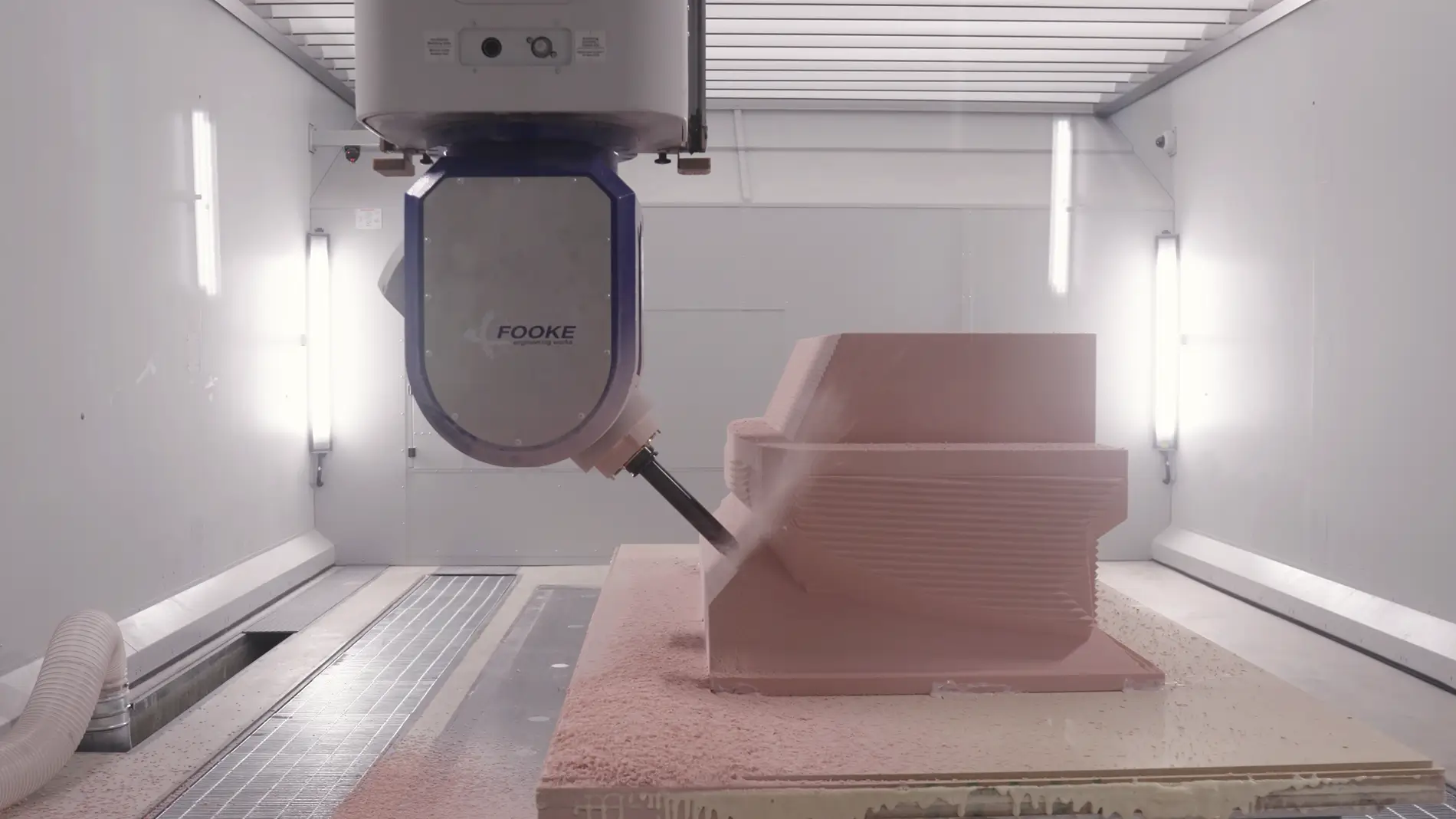
To demonstrate the past, they had a plywood mockup of a generic prototype vehicle with real seats installed. This was the “old” method to test spacing, roominess, and sightlines. The new method involves the use of 3D foam cutting, painting, and fabricated metal parts to make mockups that are more accurate than ever before. Small design changes can be precisely iterated.
Battery Lab
This area was still under development, but had several environmental chambers for battery cell testing. They also had a laser welder (for welding cell tabs), and a glove box (inert atmosphere) for dissembling cells. The centerpiece was a large overhead crane assembly, this would be used to lift cell modules and battery packs. They said this is where they can explore different battery pack assembly methods.
Thermal Lab
This area has several large environmental test chambers for testing the extremes of temperature on components. Some of the chambers was large enough to contain an entire battery pack or subassembly. One was large enough to contain an entire vehicle, and has solar lighting installed (to simulate the heat of the sun). They said they will test the vehicles in temps ranging from -40ºC to +60ºC.

The crown jewel here was a very large (small house size) environmental chamber being built around a rolling AWD dynamometer. The car sits in the center with wheels spinning on the rollers. This high-precision dynamometer is capable of simulating whatever speed and road load profiles they want. Other features are a gigantic fan for simulating wind, and there will be a full solar array installed near the ceiling of the chamber to simulate solar loads. There will also be a high-power DC fast charger installed immediately adjacent to recharge vehicles on the dyno, with high-fidelity energy monitoring. For example, they can simulate the road load of driving up a mountain on a hot day and then immediately DC fast charging to stress the vehicle thermal systems. This dyno will also be certified for EPA range testing (it will run the EPA test cycles, every Wh measured), so Ford can determine the MPGe and range that goes on the window sticker.
High Voltage and Electrical Lab
This lab was the most technologically advanced. There were racks of electronics equipment, wires going everywhere. Lots of test equipment and soldering stations for working on circuit boards. More environmental test chambers with battery cells inside. They were currently running an EPA discharge cycle on a test cell, monitoring voltage and current. On a table they had a few high voltage components out on display us, a motor inverter, the Ebox, and the charge port. The Ebox contains the high voltage contactors, as well as the on-board charger, DC/DC converter (48V output), and inverter for AC output/bidirectional charging. There are liquid cooling ports on the end of it for the power electronics, it’s essentially an extra-long HVBJB but overall much smaller than the size of the legacy parts it would replace. The charge port was very interesting—it’s a NACS port with a locking mechanism, but they have also integrated a local body module on the backside of it, a 2-in-1. There are wire harness connectors at the bottom back of it, these might be used to power nearby body components such as the charge port door and the taillights. Interesting design choice for sure.
There was a brief stop with a Faraday tent and dipole antenna for testing spurious RF emissions of electronics. Basically, they can make sure the power electronics are not going to cause interference to AM/FM radio, broadcast, or military radio frequencies.
The next station was my favorite—it showed the new heat pump and thermal/HVAC system installed in the front unicasting. All the coolant hoses were hooked up for testing in an environmental chamber. The big news here is Ford has designed an integrated coolant manifold that is the size of a large textbook (contains several pumps and valves in one). This would be Ford’s equivalent of the Tesla Octovalve. This manifold is the consolidated solution to all the crazy coolant piping and pumps everywhere in the current generation Ford EVs. All the inputs/outputs are consolidated on the left side (looks like about four loop pairs), and the run to heater core is much more direct. There were two plate heat exchangers or chillers, I presume one for water-to-refrigerant and the other for water-to-water heat transfer. They said with this setup they can basically transfer heat to and from whatever components they need to (e.g. motor to cabin, charger to battery, etc.)
Closeup of new coolant manifold:
The compressor is mounted right next to the coolant manifold on the same frame, EEVs right there too. Another big new feature they announced is the heat pump is capable of vapor injection or hot gas bypass. This is a feature of cold weather heat pumps, and allows the heat pump to continue operating and essentially generate its own heat down to a colder ambient temperature. They said this will allow the elimination of the PTC heater, although the prototype still had a PTC heater installed. Hopefully this new thermal system is up to keeping the cabin and battery warm even in harsh Canadian arctic temps, while being more efficient.
The thermal system was packaged nicely along the firewall, this should allow there to be a small frunk space in front of it. Probably not much bigger than medium duffle bag, but that’s the tradeoff for having a heat pump.
Wiring Integration Lab
There were several body components from the truck connected together with wiring harnesses (headlights, taillights, window regulators, switches, steering wheel, touchscreen) on a test grid. This is used to test for any mistakes in a device’s pinout (such as swapped signal and ground pins) and to integrate all the modules together and make sure they talk to each other as expected. The electrical system is primarily 48VDC (which reduces wire size and cost), although there may still be some 12V components in places.
I saw some interesting things here. Speculation warning, none of this is confirmed. The center touchscreen was covered, but is horizontal. There was not a separate instrument cluster screen (but perhaps it had been removed). The steering wheel was there, and the buttons on it seem to be a new layout for Ford. Rather than defined buttons, there was a small scroll wheel on each side, and also a left and right arrow button on each side. Still had stalks on both sides as well. That’s about it. That would support the presence of a more software defined UI experience. The thumbwheels and screen remind me of a Tesla Model 3/Y (also sans instrument cluster?).
The NACS charge port was in the left rear of the vehicle layout.
The wiring mockup was being powered by a power supply installed in the location of the Ebox (backseat area). I did not see any low voltage battery in the setup. Nor did I see any provisions for one. The DC/DC is in the Ebox, so ideally the LVB would be located close by. Wonder if they figured out a way to eliminate a LVB, we’ll see.
Harness Lab
Here they can build whatever wire harness they need, with whatever connectors they need. Pretty self-explanatory. Spools of wire, bins of connectors and pins, soldering/test station. They were building a harness on a board with nails for each intersection.
Metrology Lab
Metrology is the science of measurement. This lab has several machines for measuring dimensions and properties of materials. First shown was a handheld 3D laser scanner which can measure and verify part dimensions. A center console was scanned for a demo. They had a universal testing machine or tensile tester. They pulled a piece of metal plate apart with it to measure the stress-strain curve. They also had a large industrial CT scanner, which can see inside parts. This can be usual for finding voids or electrode defects, also for examining for cracked solder joints, among many uses. They also had a measuring microscope, turntable 3D scanner and a laser-induced breakdown spectrometry (LIBS) machine for determining elemental composition.
Fleet Center
Last was a large garage with about six two-post lifts. They said these are used to work on prototype vehicles and test mules. For example, they can raise or take apart vehicles to install extra instrumentation sensors. The technician recalled recently installing over 500 thermocouples at various places in the vehicle for real-world thermal testing.
Conclusion
On our walk back to the entrance, we were surprised by a camouflaged test mule of the truck. To put some things in perspective, it looked bigger than a Maverick but smaller than a Ranger. Similar ground clearance, probably around 8”. The front looked more like a rounded SUV nose rather than the boxy truck (but not ugly). Roof had the distinctive curved down slope and the bed looked about the same length as the maverick (4.5’). They supposedly have stated test production and final validation with about 100 units scheduled. They still anticipate a mid 2027 release for the truck.
Overall, this was an impressive tour that showcased Ford’s investment in EVs and the future of the company. There were a lot of expensive machines here. But overall, the EVDC feels much like a smaller start-up engineering firm. I guess that’s the best of both worlds, small company vibe with the freedom to do things their way, but backed by the major capital of Ford. I liked what I saw, overall these guys should have the tools at their disposal to make a great EV.
Sponsored
Last edited:
![Ford Mustang Mach-E A visit to the Skunkworks (Ford's EVDC) -- behind the scenes tour UEV Cultural Commandments_Finalv2_RGB[74][55]](https://cdn.macheforum.com/attachments/163/163484-ce95ac690a589ca422bd439b5128f961.webp)

 .
.
 But if they call me up at 3 am and ask where to put the NACS port, my answer will be "right front." If the vehicle can tow, it needs to be on the right front.