louibluey
Well-Known Member
- First Name
- Joe
- Joined
- Dec 21, 2020
- Threads
- 60
- Messages
- 888
- Reaction score
- 1,127
- Location
- NY
- Vehicles
- FE "Louibluey" GB
- Occupation
- retired
- Thread starter
- #1
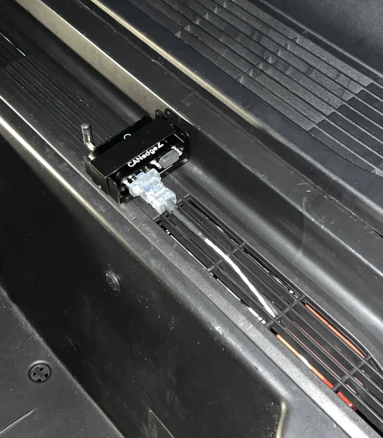
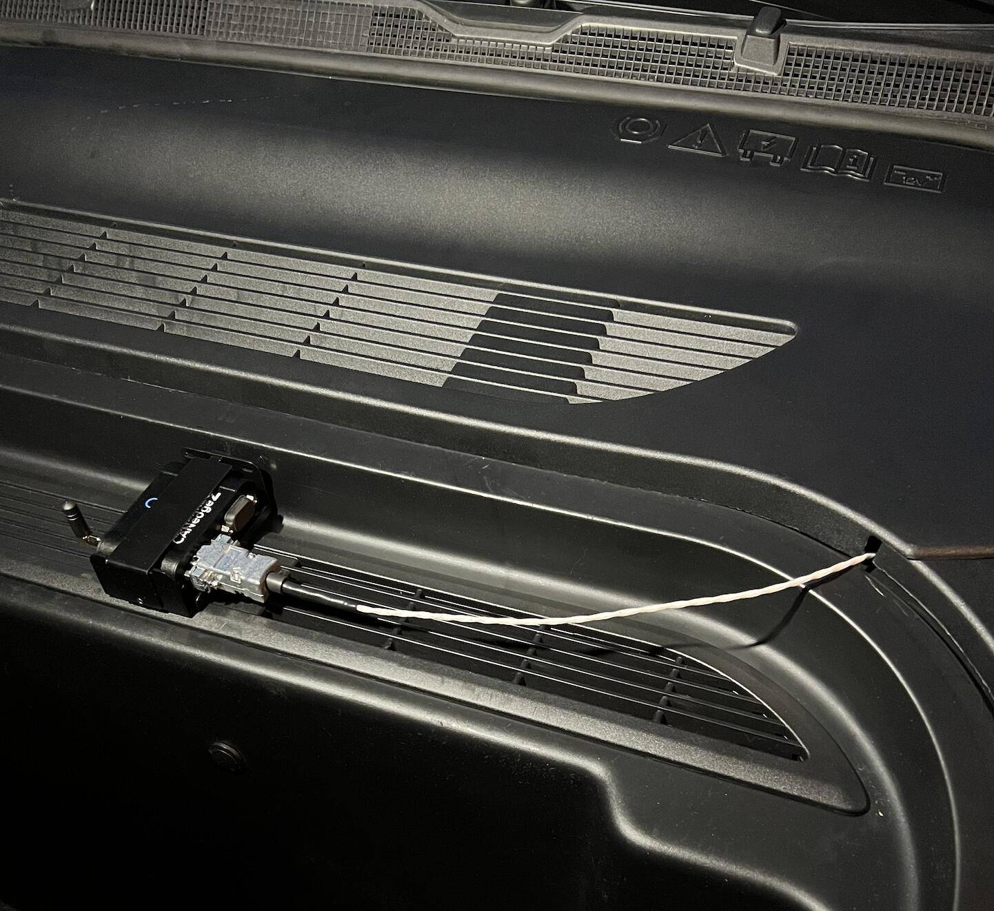
First look at a MME LIN BUS device for me, I will update with information as I learn how to decode this first example.
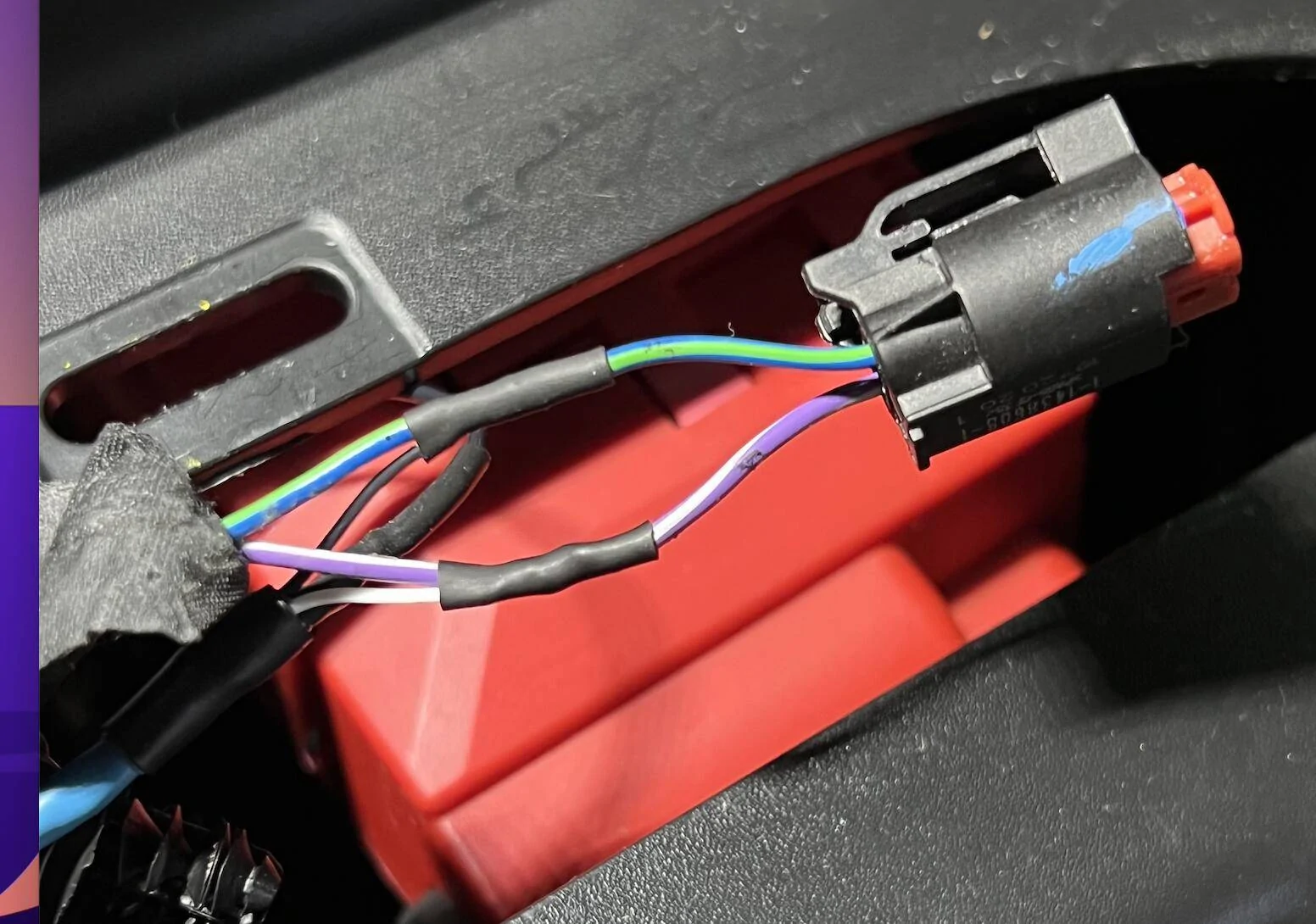
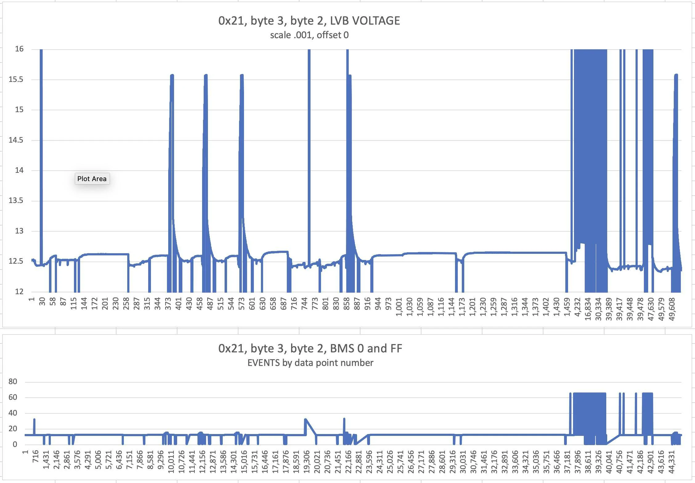
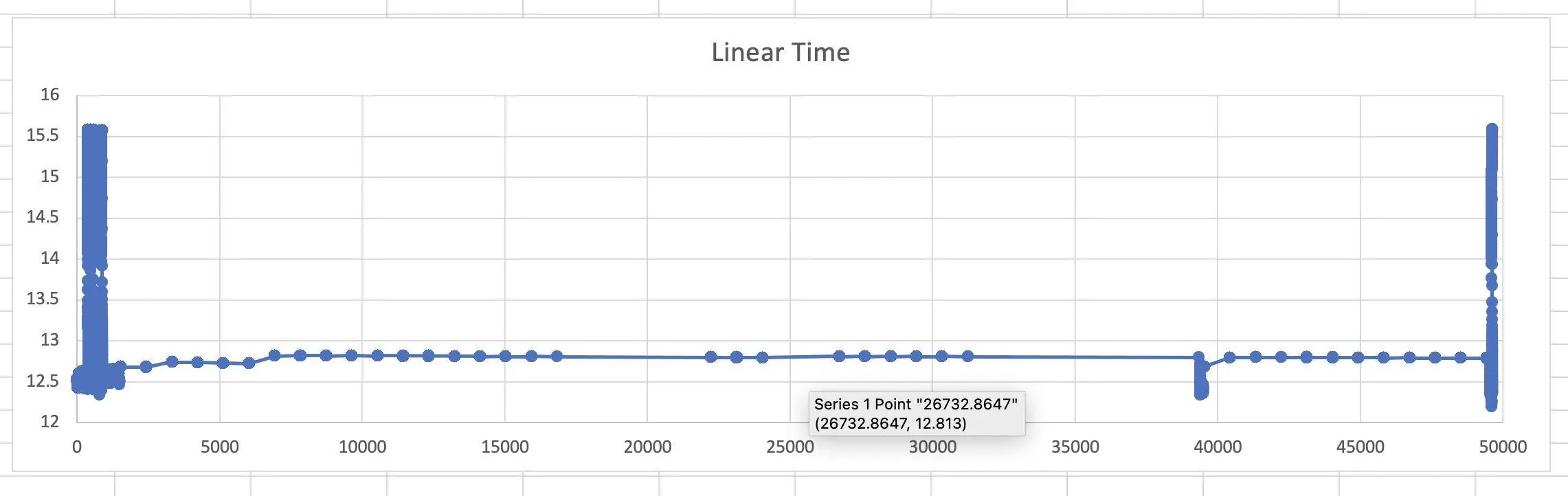
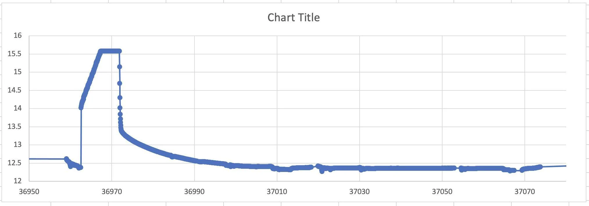
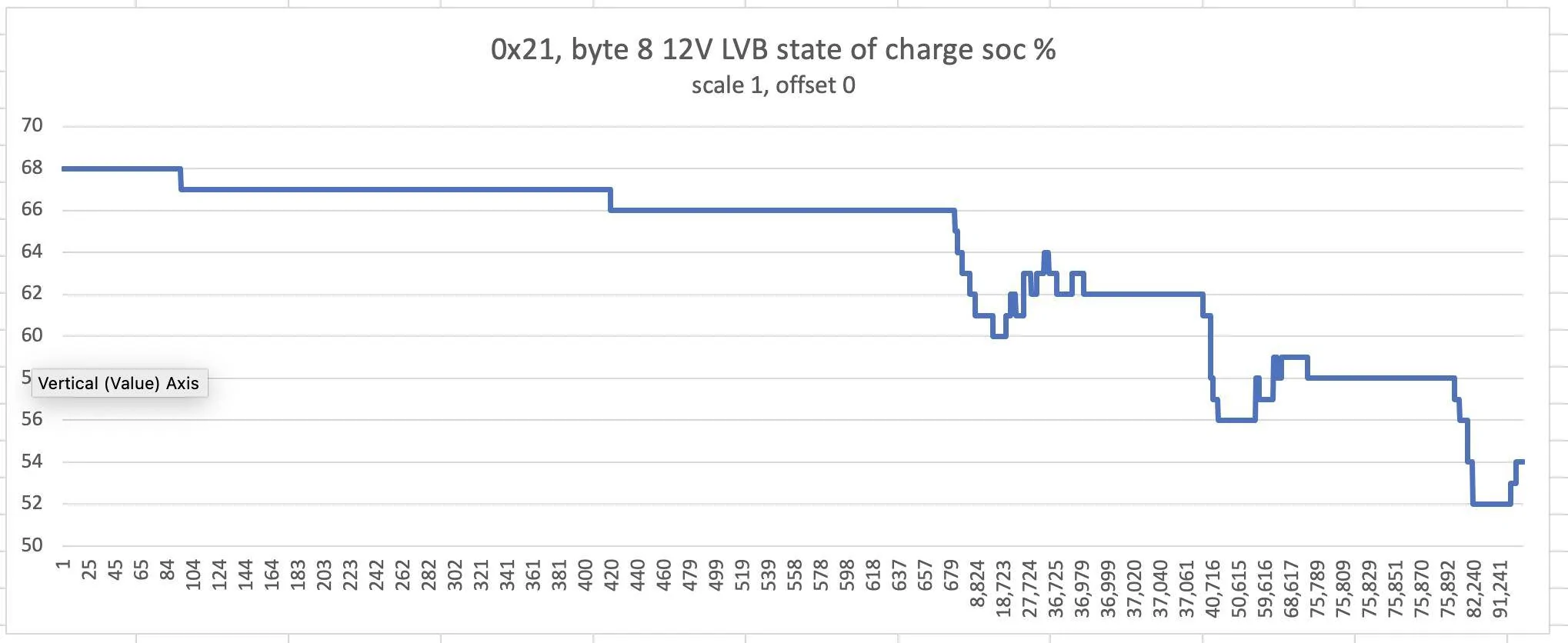
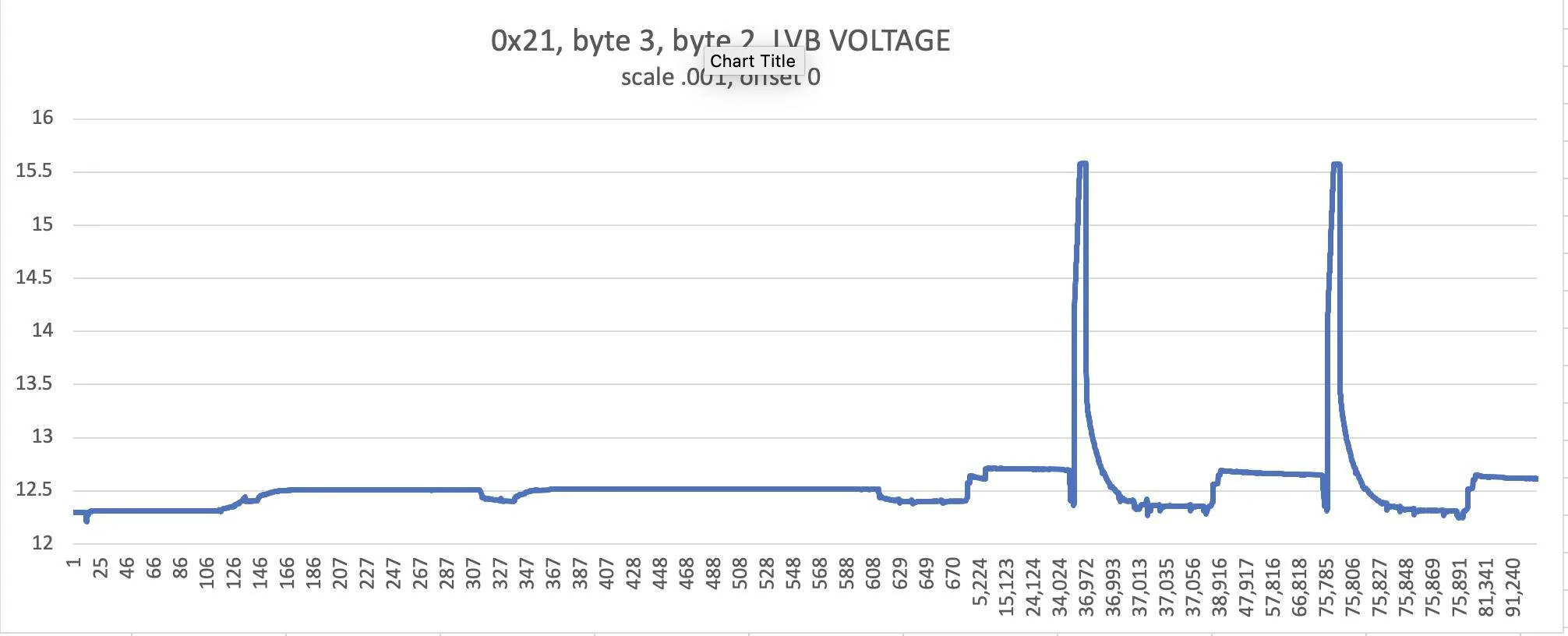
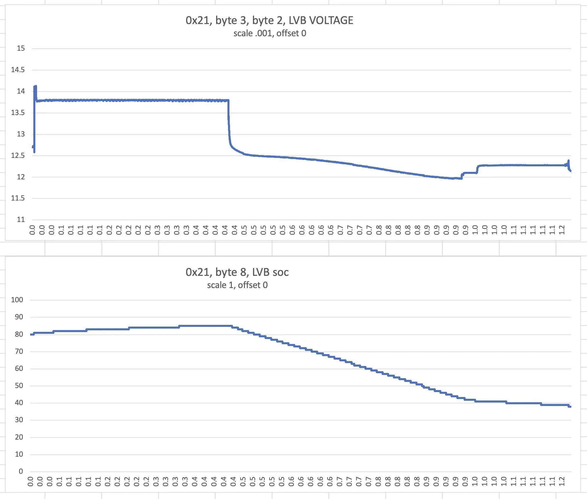
Tapped into the BMS LIN BUS here, but starting a new LIN dedicated thread. This will be of limited interest to most, but maybe some more general things can be learned, such as about LVB voltage reporting. For example, already noticing that the BMS (the sensor on the 12V battery negative terminal) stops reporting when MME is resting. That means that some monitoring via APIs and Apps is probably reporting the last value before MME went to rest. BMS reports at least voltage, current, and temperature. I think it also reports 12V LVB state of charge (soc) and possibly more.
(note: the regular continuous BMS reporting goes off during rest/sleep. It is still possible that the body control module occasionally asks for an update on some slow time schedule. Later data logging with the CSS electronics CANedge2 LIN logger should answer this question later).
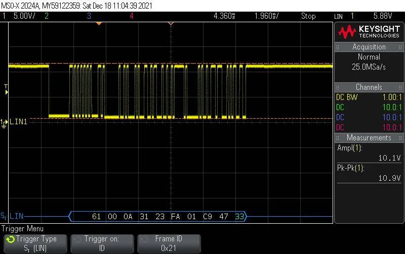
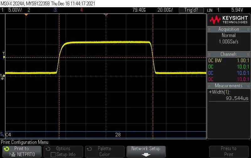
First step is measure the LIN BUS baud rate. The Master (body control module) sends the rate and the slave uses that rate. I noticed during initial viewing that 10.4 kbs was working, however on closer look, at least my MME FE seems to be running about 10.7 kbs.

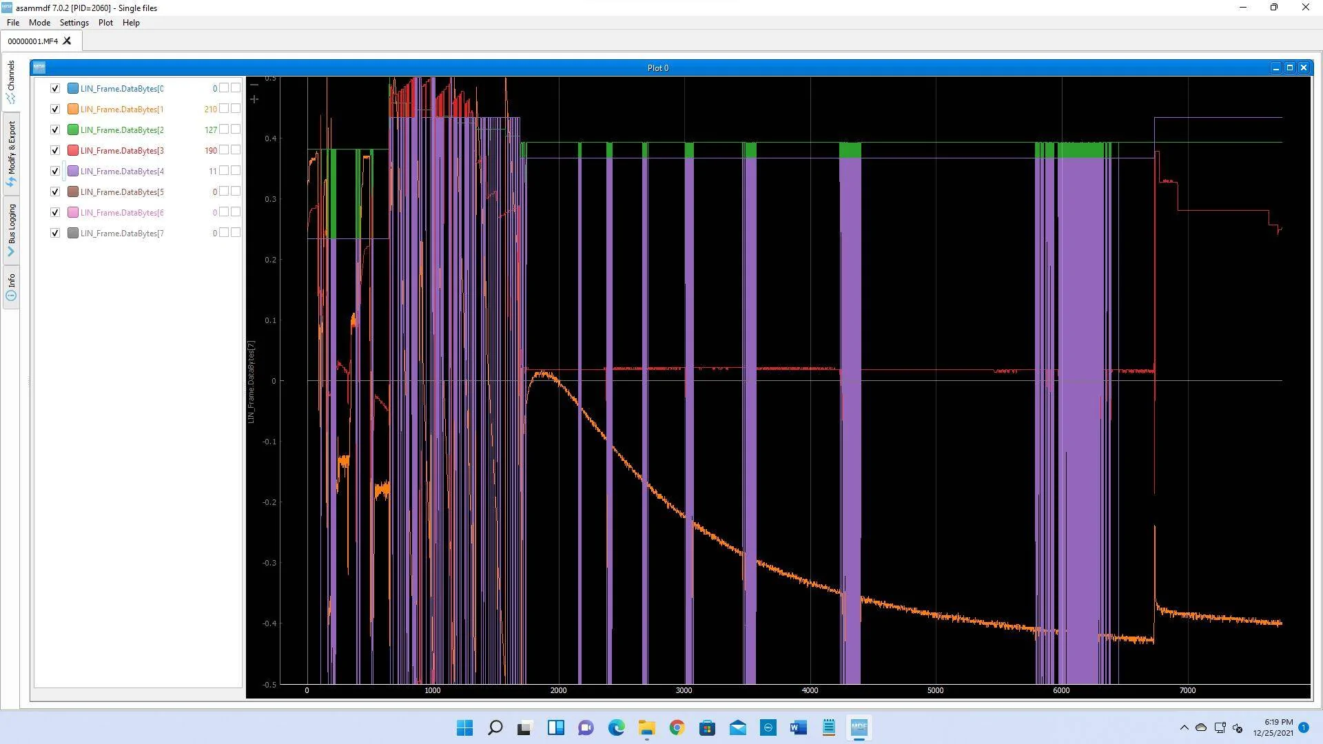
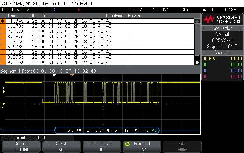
Using an oscilloscope with serial LIN decode for this first look. Here is an example set to trigger on device 25 (I think). The white hex numbers are the 8 data fields.
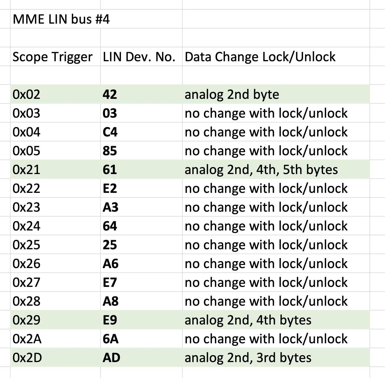
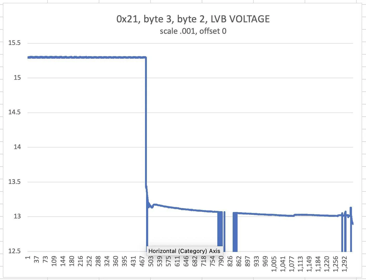
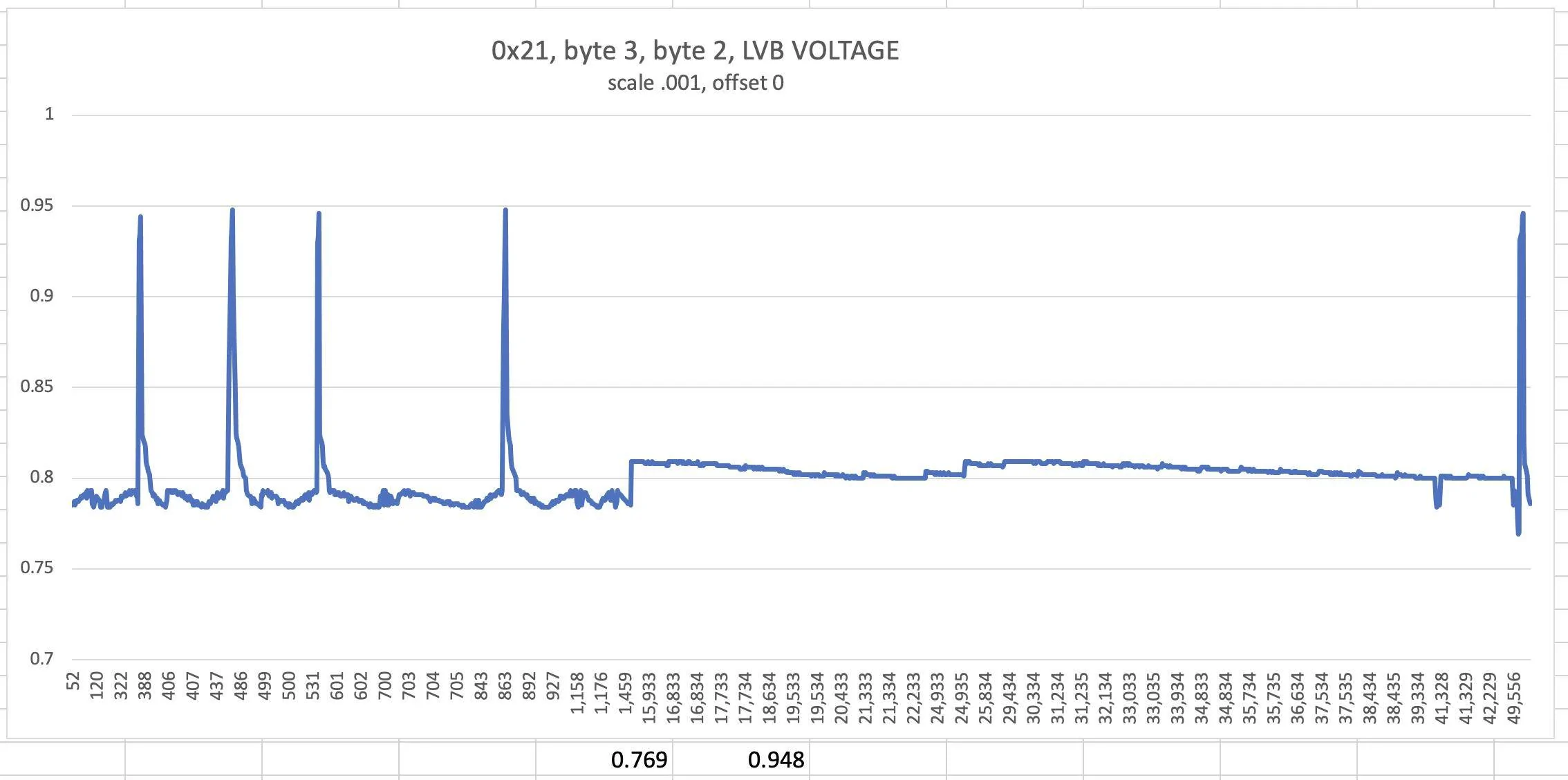
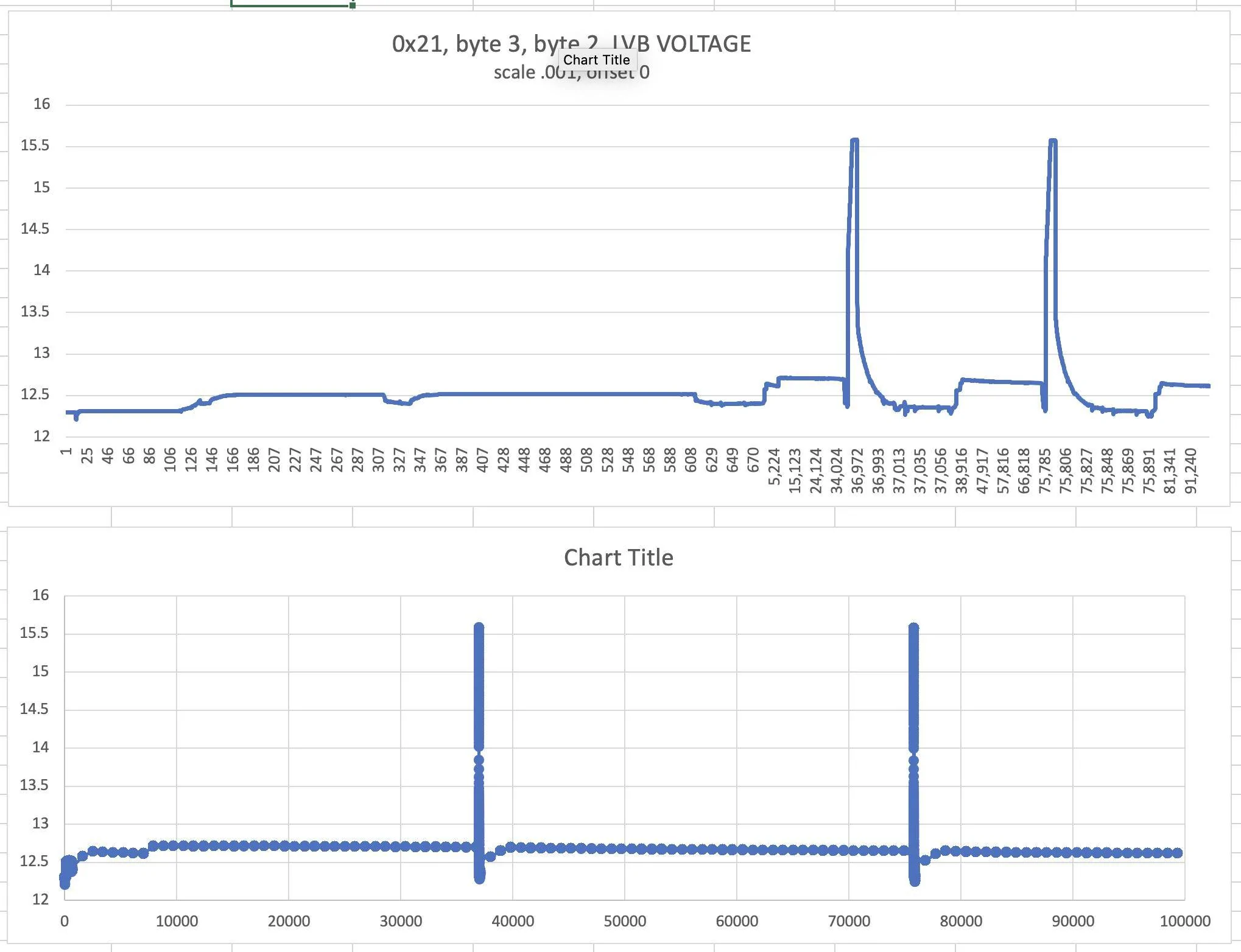
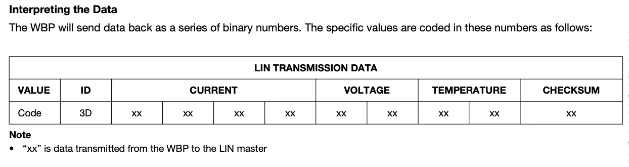
Locating the BMS device number(s) is the next job, then identifying its data fields (voltage, current, temperature) and any offset and scale factors. For some reason it seems difficult to look this up, for BMS data sheets which do not show that detail to the chip data sheets which are so detailed, it is difficult to answer this simple question. Here is an example of a Vishay sensor, which is likely different, but the kind of info needed for our MME BMS device.

Tapped into the BMS LIN BUS here, but starting a new LIN dedicated thread. This will be of limited interest to most, but maybe some more general things can be learned, such as about LVB voltage reporting. For example, already noticing that the BMS (the sensor on the 12V battery negative terminal) stops reporting when MME is resting. That means that some monitoring via APIs and Apps is probably reporting the last value before MME went to rest. BMS reports at least voltage, current, and temperature. I think it also reports 12V LVB state of charge (soc) and possibly more.
(note: the regular continuous BMS reporting goes off during rest/sleep. It is still possible that the body control module occasionally asks for an update on some slow time schedule. Later data logging with the CSS electronics CANedge2 LIN logger should answer this question later).
First step is measure the LIN BUS baud rate. The Master (body control module) sends the rate and the slave uses that rate. I noticed during initial viewing that 10.4 kbs was working, however on closer look, at least my MME FE seems to be running about 10.7 kbs.
Using an oscilloscope with serial LIN decode for this first look. Here is an example set to trigger on device 25 (I think). The white hex numbers are the 8 data fields.
Locating the BMS device number(s) is the next job, then identifying its data fields (voltage, current, temperature) and any offset and scale factors. For some reason it seems difficult to look this up, for BMS data sheets which do not show that detail to the chip data sheets which are so detailed, it is difficult to answer this simple question. Here is an example of a Vishay sensor, which is likely different, but the kind of info needed for our MME BMS device.
Sponsored
Last edited: