Mach-Lee
Well-Known Member
- First Name
- Lee
- Joined
- Jul 16, 2021
- Threads
- 262
- Messages
- 11,413
- Reaction score
- 25,173
- Location
- Wisconsin
- Vehicles
- 2022 Mach-E Premium AWD
- Occupation
- Sci/Eng
- Thread starter
- #1
I had a request to look at my charging temps at 40-48A, so I decided to do that and share results of what is considered "normal" as a baseline for comparison. Some Mach-E are having problems L2 charging at 40+A due to software issues, hardware issues, EVSE issues, or some combination. I will be comparing values collected in the Car Scanner app and with FDRS (Ford's official scan tool software). Heads-up, there are some problems with the parameters in Car Scanner.
Temps are in Celsius because that's what us engineer types use. I'll convert some important values to F, but just be aware of unit differences if you are comparing with Car Scanner and you have it set to F instead of C.
I talk more about hardware at the end, but there are two main things that get hot while Level 2 charging, the charge port, and the on-board charger (SOBDM) which converts the AC to DC to charge the battery. There are three temp sensors in the charge port, one for the AC pins, and one for each DC pin. And there are four internal temp sensors inside the charger module. That's it.
Initial conditions:
Charging in a 28ºC (82ºF) garage after a drive. Level 2 charger set to 44A / 10.5 kW (can't do higher due to breaker limits).

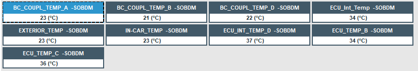
FDRS initial:

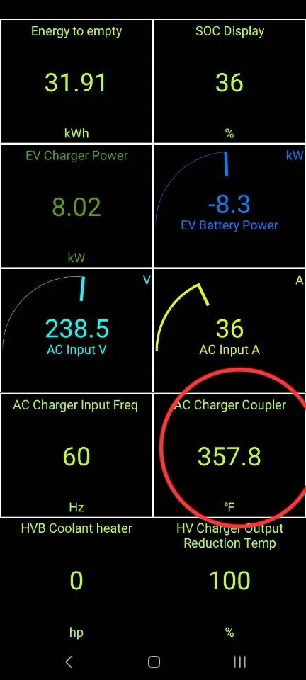
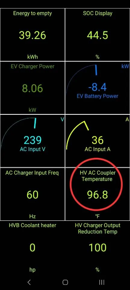
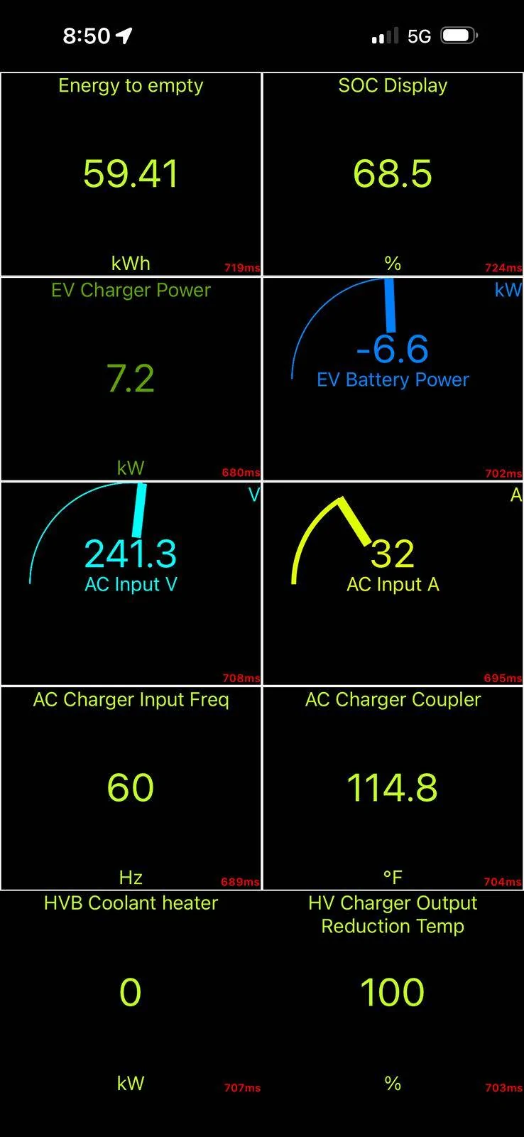
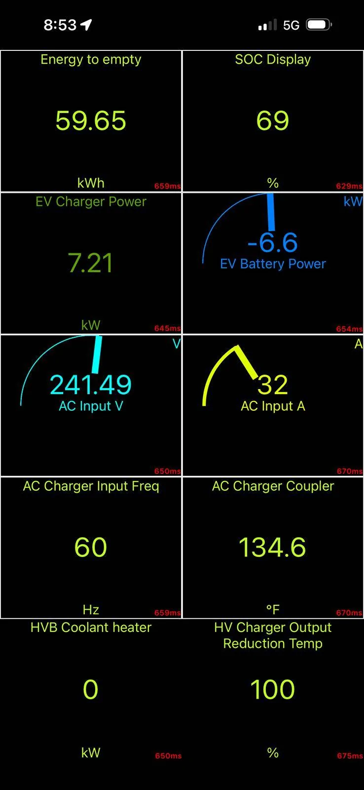
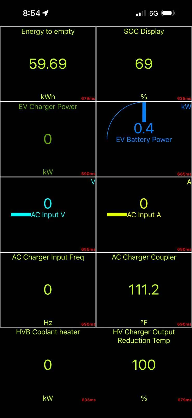
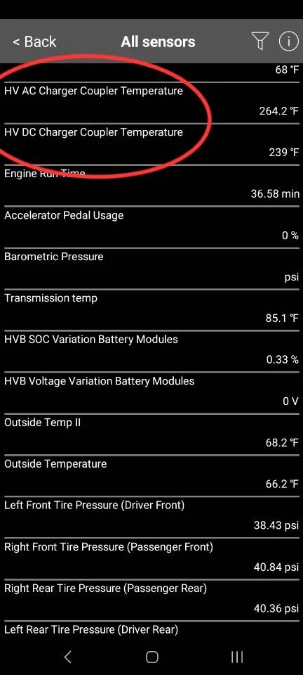
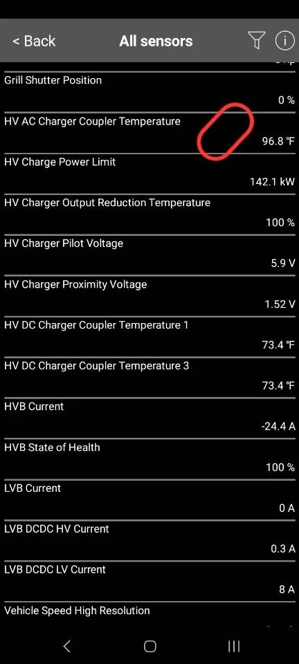
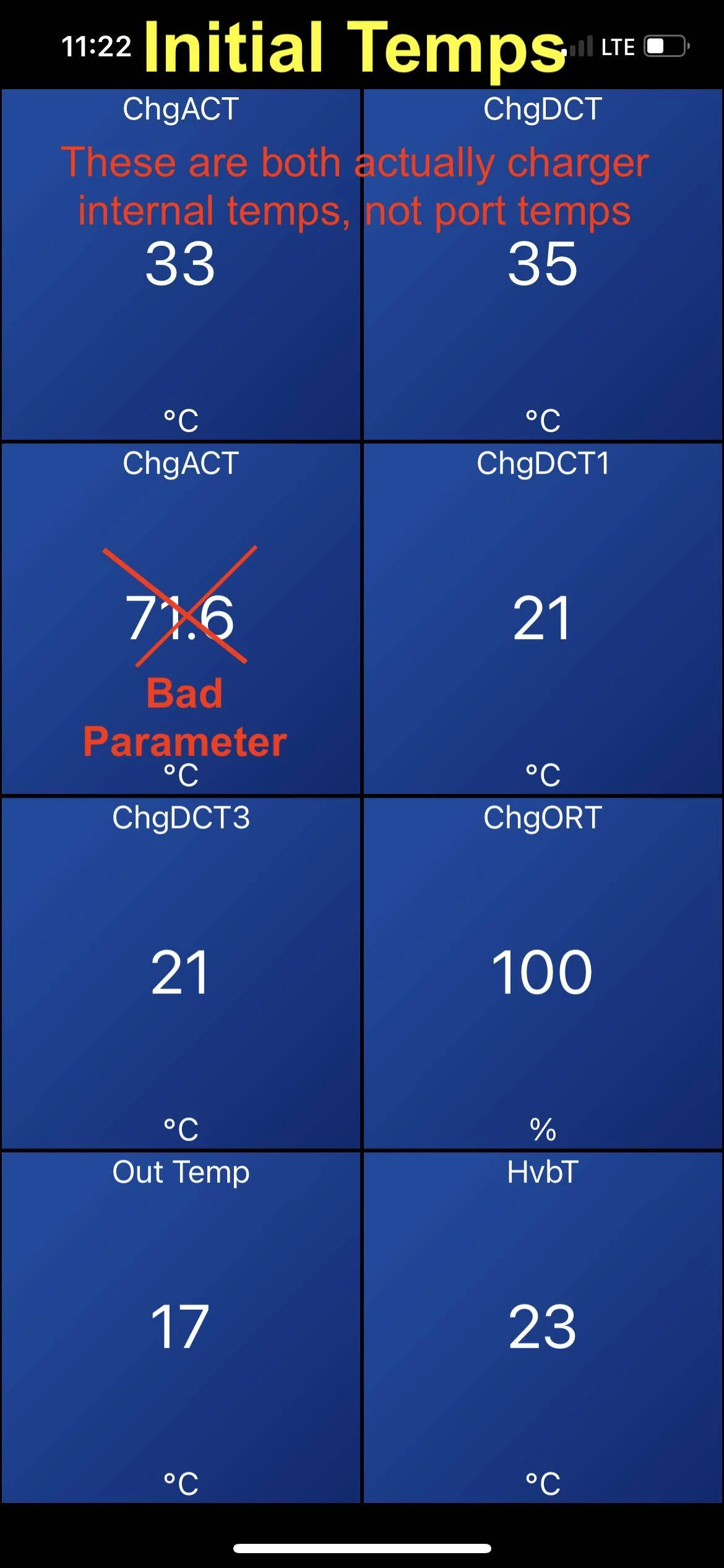
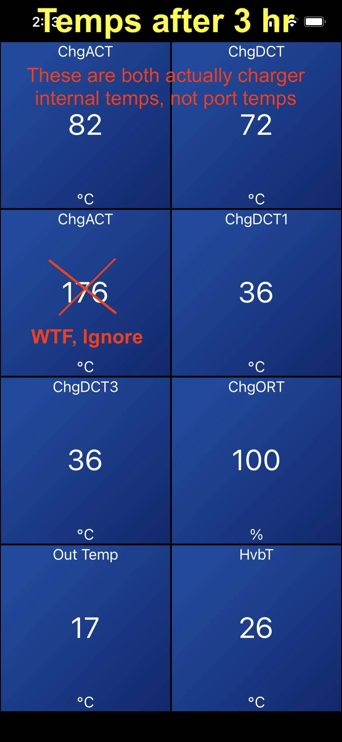
I selected all the charging temps I could find in Car Scanner. In the process, I found that Car Scanner has some of the parameters labeled incorrectly. There are two ChgACT parameters (supposed to be AC charge port temp), the first one is actually the charger internal temperature (labeled wrong) and the second parameter is total nonsense (scaled wrong). It went from 72ºC to 176ºC during charging which is not possible. Those are not the real temps, so please ignore that one, I crossed it out. The ChgDCT parameter is also wrong, that is really a second internal charger temperature. The Car Scanner developer needs to fix some of these parameters so they display correctly.
FDRS tells the true story with the parameters. The charge port started about 22ºC (72ºF), and the internal charger temp started around 35ºC (95ºF) because the car was recently driven.
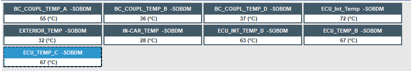
After 3 hours of charging at 44A (10.5 kW):
FDRS 3 hour temps:

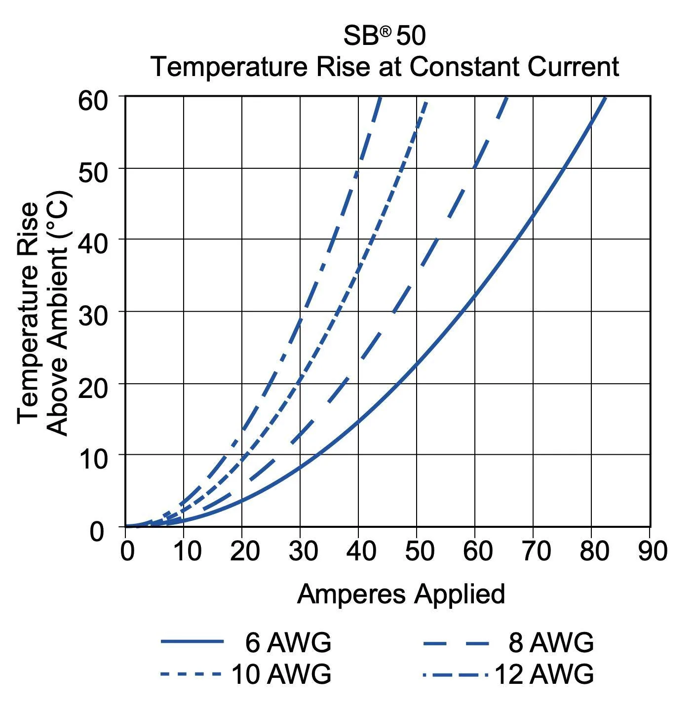
After 3 hours of 44A continuous, the AC pins in the charge port (BC_COUPL_TEMP_A) have warmed up to 55-59ºC (131-138ºF), or about 30ºC above ambient. This is reasonable. I'm using a new ChargePoint J1772 cable. The ChargePoint J1772 cables do get warmer than other brands at 40+ amps because they use smaller conductors (9 AWG). Based on the 9 AWG wire gauge and 44A current, the 50A rated contacts are performing as expected:

I don't know how hot the AC pins can get before charging slows down, but the J1772 spec says they need to handle +50ºC over ambient. Of note, Car Scanner does not actually have the parameter for AC charge port temp (remember it's labeled wrong). Only the DC pins, which aren't used for AC charging.
The DC pins (B+D) warmed up to about 36ºC just from the nearby heat generated by the AC pins. These temps are reported correctly in Car Scanner (ChgDCT1 and 3).
The four internal charger temps varied from 61-82ºC (142-180ºF). These cycle up and down with the fan (more on that later) but 82ºC/180ºF seems to be the upper limit where fans and pumps kick into high gear. The internal charger temps should not get higher than that, or charge rate may be dropped to protect the charger components from thermal damage.
Pump and Fan operation:
Let's talk about the thermal systems on the Mach-E and how they should work during charging. The on-board AC charger (located under the top frunk cover) will generate heat during the power conversion process from AC to DC. This process is about 90% efficient at 240V, so 10% of the power gets converted to heat, or about 1.1 kW of waste heat at 48A. The charger is liquid cooled, so this heat gets transferred into the motor/electronics coolant loop, and is ultimately dissipated through the other components in the loop, or through the radiator/fan. The on-board charger (SOBDM) is component #17 in the below figure:

The order of components in the AWD motor/electronics coolant loop is as follows: Reservoir, pump, on-board charger, DC/DC converter, rear motor inverter, oil heat exchanger, front motor inverter, auxiliary pump, and radiator. This varies slightly, RWD doesn't have a front motor, and on GT models the plumbing is a little different.
When you plug in and start charging in summer temp conditions, you should hear the coolant pump start running (sounds like a quiet hum). This is going to circulate heat around the loop to the other components, warming them all up. This could take some time if they are cold to start, and in cooler ambient conditions the passive thermal radiation from the components may be enough to dissipate the 1kW of heat without using the fan. Essentially the motors can act as radiators, up to a point. However if the coolant or charger internals gets too warm, then the SOBDM can request the cooling pump speed increased or the radiator fan to run. This will bring down the temps in the loop, the fan shuts off, and the cycle continues with intermittent fan use. Those of you in really hot climates like Arizona will probably see the cooling fan run continuously during charging. Or if you plug in to charge right after a drive, the coolant in the loop might be hot already from the motors, so the fan could run right away.
Now let's observe operation and look at the temps in FDRS during a fan cycle, and after charging stops.
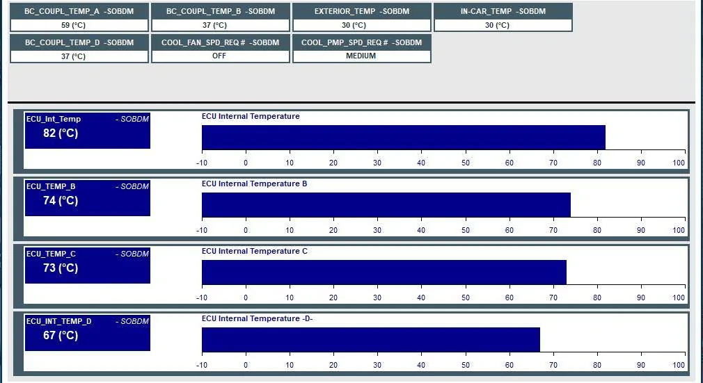
Right before the radiator fan turns on, everything is hot. Coolant pump is running at medium speed. These are peak temps:

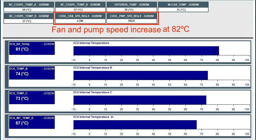
When 82ºC is reached, SOBDM requests cooling fan LOW and pump move to HIGH:
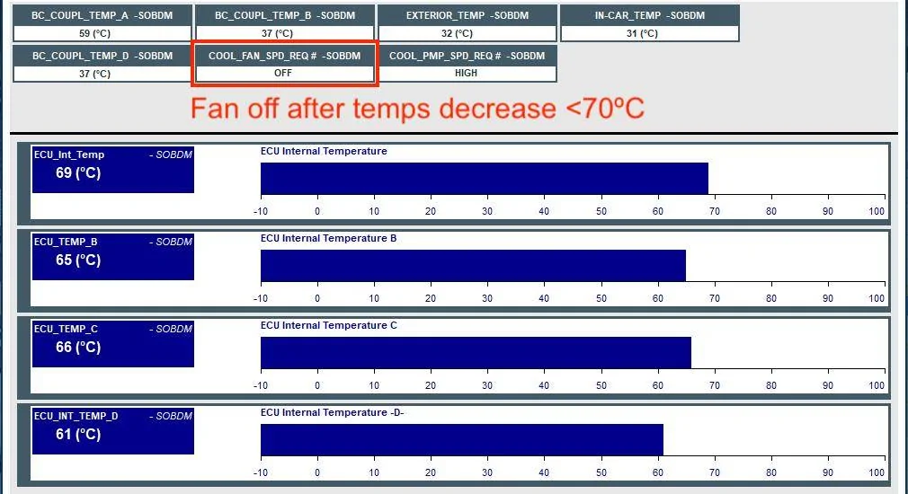
Fan runs on LOW for about 20 minutes until internal temps decrease below 70ºC, fan no longer requested:

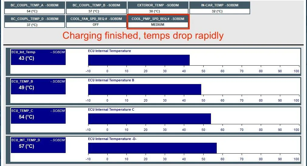
As soon as charging finishes, temps drop rapidly, pump reverts to MEDIUM.

And finally 10 minutes after charging has stopped:

The last point I'd like to make is that the charge port is not actively cooled. You can see the temp in the upper left, it stays at 59ºC the whole time (thermal equilibrium) regardless of pump speed and fan running, these do nothing. It's completely passive heat dissipation. The only thing that decreases charge port temp is reducing the charging amperage. You can see it drops rapidly as soon as charging is stopped.
If either the charge port or the charger internals are overheating, you will see the charge rate decrease or stop until things cool down enough to resume.
Temps are in Celsius because that's what us engineer types use. I'll convert some important values to F, but just be aware of unit differences if you are comparing with Car Scanner and you have it set to F instead of C.
I talk more about hardware at the end, but there are two main things that get hot while Level 2 charging, the charge port, and the on-board charger (SOBDM) which converts the AC to DC to charge the battery. There are three temp sensors in the charge port, one for the AC pins, and one for each DC pin. And there are four internal temp sensors inside the charger module. That's it.
Initial conditions:
Charging in a 28ºC (82ºF) garage after a drive. Level 2 charger set to 44A / 10.5 kW (can't do higher due to breaker limits).
FDRS initial:
I selected all the charging temps I could find in Car Scanner. In the process, I found that Car Scanner has some of the parameters labeled incorrectly. There are two ChgACT parameters (supposed to be AC charge port temp), the first one is actually the charger internal temperature (labeled wrong) and the second parameter is total nonsense (scaled wrong). It went from 72ºC to 176ºC during charging which is not possible. Those are not the real temps, so please ignore that one, I crossed it out. The ChgDCT parameter is also wrong, that is really a second internal charger temperature. The Car Scanner developer needs to fix some of these parameters so they display correctly.
FDRS tells the true story with the parameters. The charge port started about 22ºC (72ºF), and the internal charger temp started around 35ºC (95ºF) because the car was recently driven.
After 3 hours of charging at 44A (10.5 kW):
FDRS 3 hour temps:
After 3 hours of 44A continuous, the AC pins in the charge port (BC_COUPL_TEMP_A) have warmed up to 55-59ºC (131-138ºF), or about 30ºC above ambient. This is reasonable. I'm using a new ChargePoint J1772 cable. The ChargePoint J1772 cables do get warmer than other brands at 40+ amps because they use smaller conductors (9 AWG). Based on the 9 AWG wire gauge and 44A current, the 50A rated contacts are performing as expected:
I don't know how hot the AC pins can get before charging slows down, but the J1772 spec says they need to handle +50ºC over ambient. Of note, Car Scanner does not actually have the parameter for AC charge port temp (remember it's labeled wrong). Only the DC pins, which aren't used for AC charging.
The DC pins (B+D) warmed up to about 36ºC just from the nearby heat generated by the AC pins. These temps are reported correctly in Car Scanner (ChgDCT1 and 3).
The four internal charger temps varied from 61-82ºC (142-180ºF). These cycle up and down with the fan (more on that later) but 82ºC/180ºF seems to be the upper limit where fans and pumps kick into high gear. The internal charger temps should not get higher than that, or charge rate may be dropped to protect the charger components from thermal damage.
Pump and Fan operation:
Let's talk about the thermal systems on the Mach-E and how they should work during charging. The on-board AC charger (located under the top frunk cover) will generate heat during the power conversion process from AC to DC. This process is about 90% efficient at 240V, so 10% of the power gets converted to heat, or about 1.1 kW of waste heat at 48A. The charger is liquid cooled, so this heat gets transferred into the motor/electronics coolant loop, and is ultimately dissipated through the other components in the loop, or through the radiator/fan. The on-board charger (SOBDM) is component #17 in the below figure:
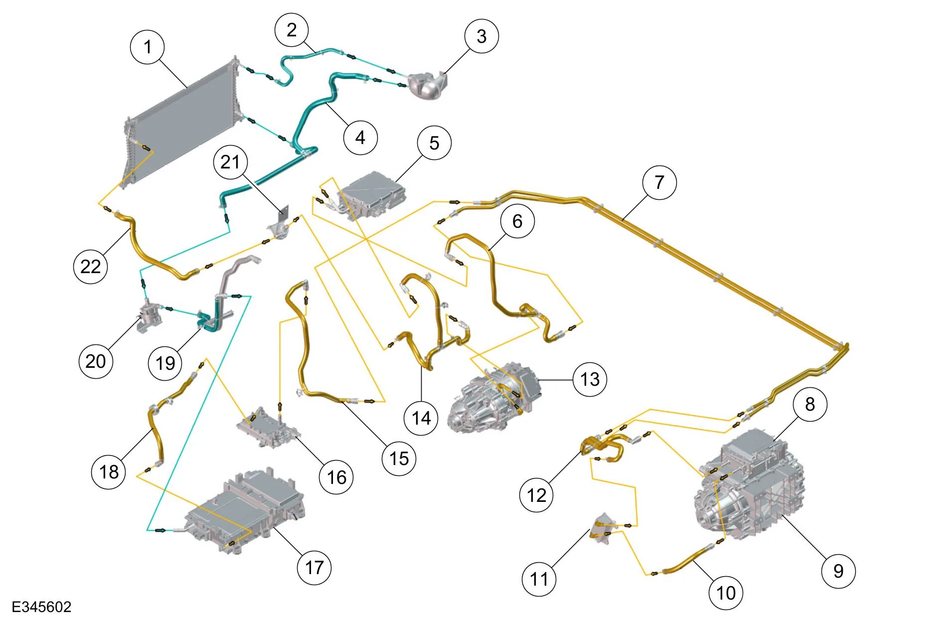
The order of components in the AWD motor/electronics coolant loop is as follows: Reservoir, pump, on-board charger, DC/DC converter, rear motor inverter, oil heat exchanger, front motor inverter, auxiliary pump, and radiator. This varies slightly, RWD doesn't have a front motor, and on GT models the plumbing is a little different.
When you plug in and start charging in summer temp conditions, you should hear the coolant pump start running (sounds like a quiet hum). This is going to circulate heat around the loop to the other components, warming them all up. This could take some time if they are cold to start, and in cooler ambient conditions the passive thermal radiation from the components may be enough to dissipate the 1kW of heat without using the fan. Essentially the motors can act as radiators, up to a point. However if the coolant or charger internals gets too warm, then the SOBDM can request the cooling pump speed increased or the radiator fan to run. This will bring down the temps in the loop, the fan shuts off, and the cycle continues with intermittent fan use. Those of you in really hot climates like Arizona will probably see the cooling fan run continuously during charging. Or if you plug in to charge right after a drive, the coolant in the loop might be hot already from the motors, so the fan could run right away.
Now let's observe operation and look at the temps in FDRS during a fan cycle, and after charging stops.
Right before the radiator fan turns on, everything is hot. Coolant pump is running at medium speed. These are peak temps:
When 82ºC is reached, SOBDM requests cooling fan LOW and pump move to HIGH:
Fan runs on LOW for about 20 minutes until internal temps decrease below 70ºC, fan no longer requested:
As soon as charging finishes, temps drop rapidly, pump reverts to MEDIUM.
And finally 10 minutes after charging has stopped:
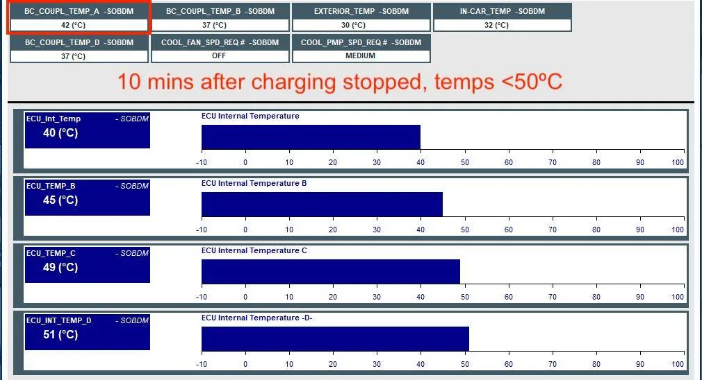
The last point I'd like to make is that the charge port is not actively cooled. You can see the temp in the upper left, it stays at 59ºC the whole time (thermal equilibrium) regardless of pump speed and fan running, these do nothing. It's completely passive heat dissipation. The only thing that decreases charge port temp is reducing the charging amperage. You can see it drops rapidly as soon as charging is stopped.
If either the charge port or the charger internals are overheating, you will see the charge rate decrease or stop until things cool down enough to resume.
Sponsored
Last edited: