JohnFoxeSheets
Well-Known Member
- First Name
- John
- Joined
- Jan 29, 2022
- Threads
- 28
- Messages
- 3,403
- Reaction score
- 5,500
- Location
- San Francisco
- Website
- johnfoxesheets.com
- Vehicles
- 2022 Iced Blue Silver Mach E GT
- Occupation
- Retired Engineer
- Thread starter
- #1
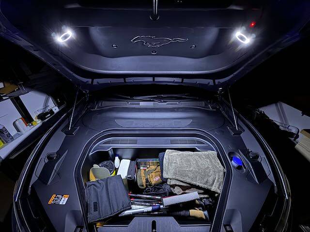
Frunk Lighting

I am not a big fan of the OEM light in the frunk. Its location inside the frunk tub means that if you keep a lot of things in your frunk like I do, items close to the light can easily shadow items further away. So I decided to add lights to the underside of the hood. I chose two halo lights because I didn’t want single light sources that would cast shadows while I am digging through the stuff in my frunk. I mounted them on the diagonal part of the under-hood trim for two reasons: 1) the mounting angles provide a nice bathing of light into the frunk, and 2) that portion of the trim has space between it and the hood, thereby giving me space for cable routing.
Caution
This modification involves tapping the 12V battery, drilling/cutting multiple holes in trim pieces under the hood/around the frunk, and running wires. Access to a 3D printer (or 3D printing service) is also required. The mod isn’t difficult per se, but it is a project and if you’re not careful, things can go wrong. If you decide to try it, please know that I cannot be held responsible for anything that might happen.
TL;DR
Feel free to jump to “Solution” if you’d rather not read about the trial and error process of getting to the solution for how best to power and control the added lighting.
Attempt #1:
Some of you may recall that I posted about a lighting project for the truck. In that project I discovered that the light module I wanted to tap had three wires, one of which is the LIN bus. As I went deep into that rabbit hole I discovered that if you wanted the added lights in the trunk to go on/off when the OEM lights do, the only practical way was to modify the light module, drilling a hole through the PCB, and adding wires and a relay. It worked, but I honestly couldn’t recommend anyone else try it. (That said, to my surprise it’s been reliable for over a year – though now that I’ve put that in writing, it will likely stop working tomorrow!)
Anyway, when I started sleuthing in preparation for the frunk lighting project, I was happy to discover that the frunk light module only has two wires – obviously 12V power, and ground. “Great!” I thought, “This’ll be easy.” I thought wrong. But so confident was I that this would be easy, I make the mod-er’s cardinal sin: I completed all wiring, cable ties, etc., before testing. Dumb. When I finally tested my handiwork, I discovered that the lighting was dim and flickered, badly. Not only were the added lights dim, but even the OWM light was dim! Clearly this wasn’t good. So I quickly removed everything and went to plan B.
Attempt #2:
You’ll recall that I needed a relay for the trunk lighting, so I figured that would work here too. It didn’t. But luckily this time I didn’t commit any sins; instead I test wired everything before I finalized it all. Good thing I did. While I was getting full brightness, the flickering was terrible, made worse by the relay. It turns out that the frunk light is pulse modulated. I.e., it is not driven either on or off; instead it is constantly turned on and off to save power. So a relay wasn’t going to do a great job here either. Time to move on to plan C.
Solution:
I decided to make my added light completely independent of the existing frunk light. To do this, I needed to be able to switch the lights on and off either manually, or with the opening/closing of the hood…….or both, which is what I did. I tried to find a way to piggy back off the existing hood open signal, but couldn’t find it and I didn’t want to start taking apart more than the usual three trim panels and frunk tub. So I added a switch that is triggered by the hood closure. I call this the cutoff switch. (More below on where the switch is mounted and how it’s activated.) And since I decided I didn’t want the lights to necessarily always come on when the hood is open (or stay on if the hood needs to stay open), I added another switch in series with the cutoff switch. I call this the manual switch.
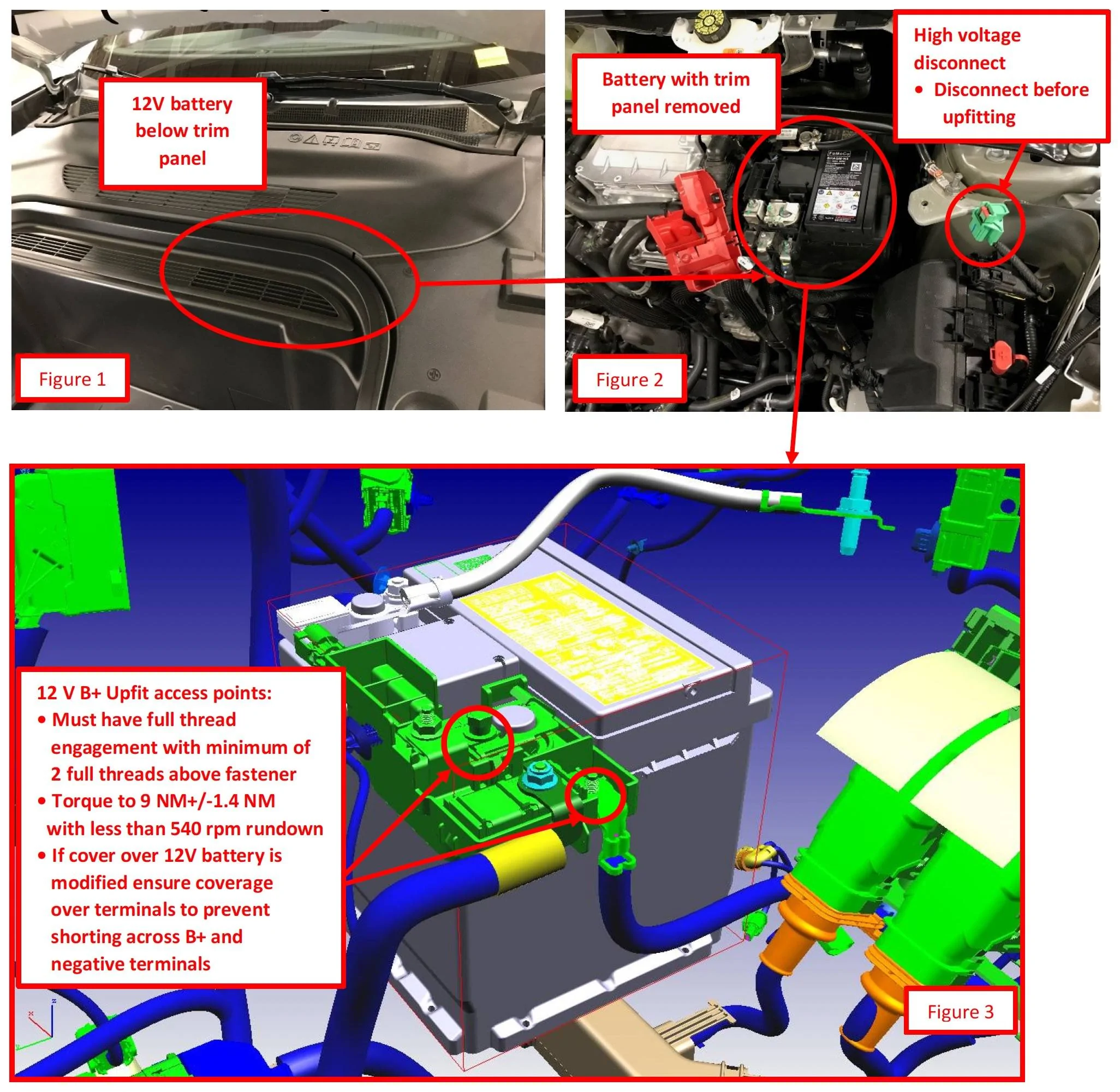
For power I tapped directly off the 12 V B+ Upfit access points. Honestly this is a bit of a PITA because the red cover over these contacts is very hard to remove and sits very tightly against the OEM cables. But it can be done – it just takes some......patience.

From P-033 Ford Police Modifier Bulletin
Once I’d tapped the 12V I connected the wire to an inline fuse block. From then it went to the Cutoff Switch and then it paired with the ground wire to go up the driver side hinge assembly and snaked up under the hood trim piece (which thankfully is not terribly difficult to remove). From there it goes to the manual switch that I installed near the driver side halo light I installed, and then to the lights themselves.
Tapping ground is much easier than the 12V since pretty much any bare metal in the car is ground. However, I decided to not try to tap the hood itself for a couple of reasons: 1) it has no electrical parts so ground is not necessarily carried reliably to the hood (it presumably wouldn’t be a design requirement), and 2) there aren’t any good tap points on the hood. Besides I had to run the power wire up from the frunk are to the hood, so running a two-wire cable wasn’t really any more difficult.
That’s it, really. Of course, doing the actual work took a lot of time and effort.
Now on to the details with photos, but first the parts lists…
Parts
(2) Halo Lights (I chose these due to their small size and the fact that they have both white and yellow lights. However the yellow is way too yellow and the white is very cold with a slight bluish tinge. I tried using both simultaneously but there was virtually no difference from just the white. That, plus the fact that it would double the current consumption, I decided to use only the white.)
18AWG Low Voltage LED Cable
(1) Cutoff (Limit) Switch
(2) Nuts for Cutoff Switch
(1) Manual Switch (comes with mounting nut)
Wire Harness Cloth Tape
Square Self-Adhesive Cable Tie Mount Bases
Cable Ties (assorted)
3D Printed Parts (The STL files for the 3D printed parts are attached in a ZIP file)
(2 each) Halo Light Housing with Diffuser (sized specifically for the above Halo Lights; if you decide to use a different light, you’ll likely need to either modify or create your own housing and diffuser)
(1 each) Cutoff Switch Activator Bumper (mates with the Cutoff Switch Activator)
Detailed Photos
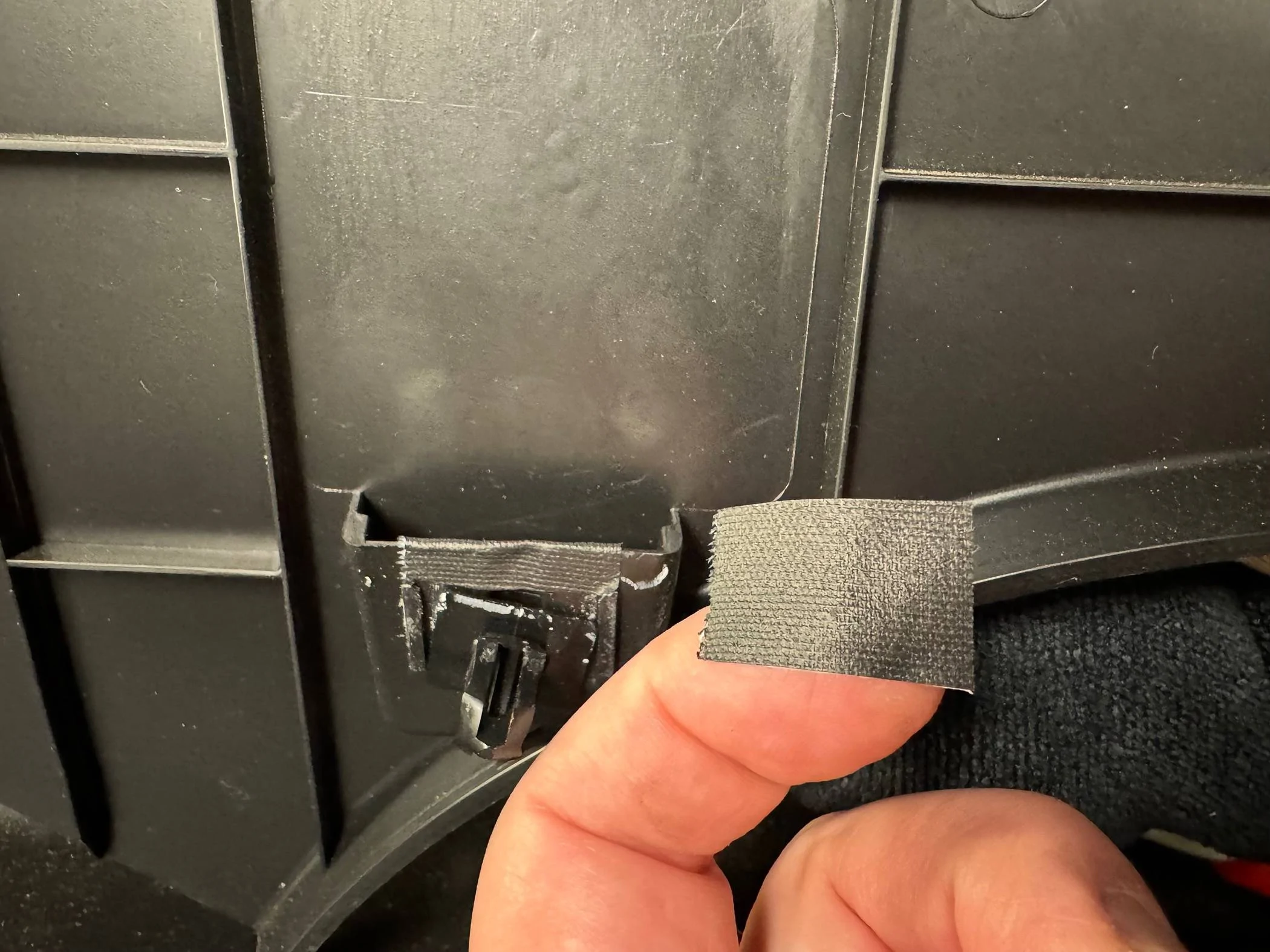
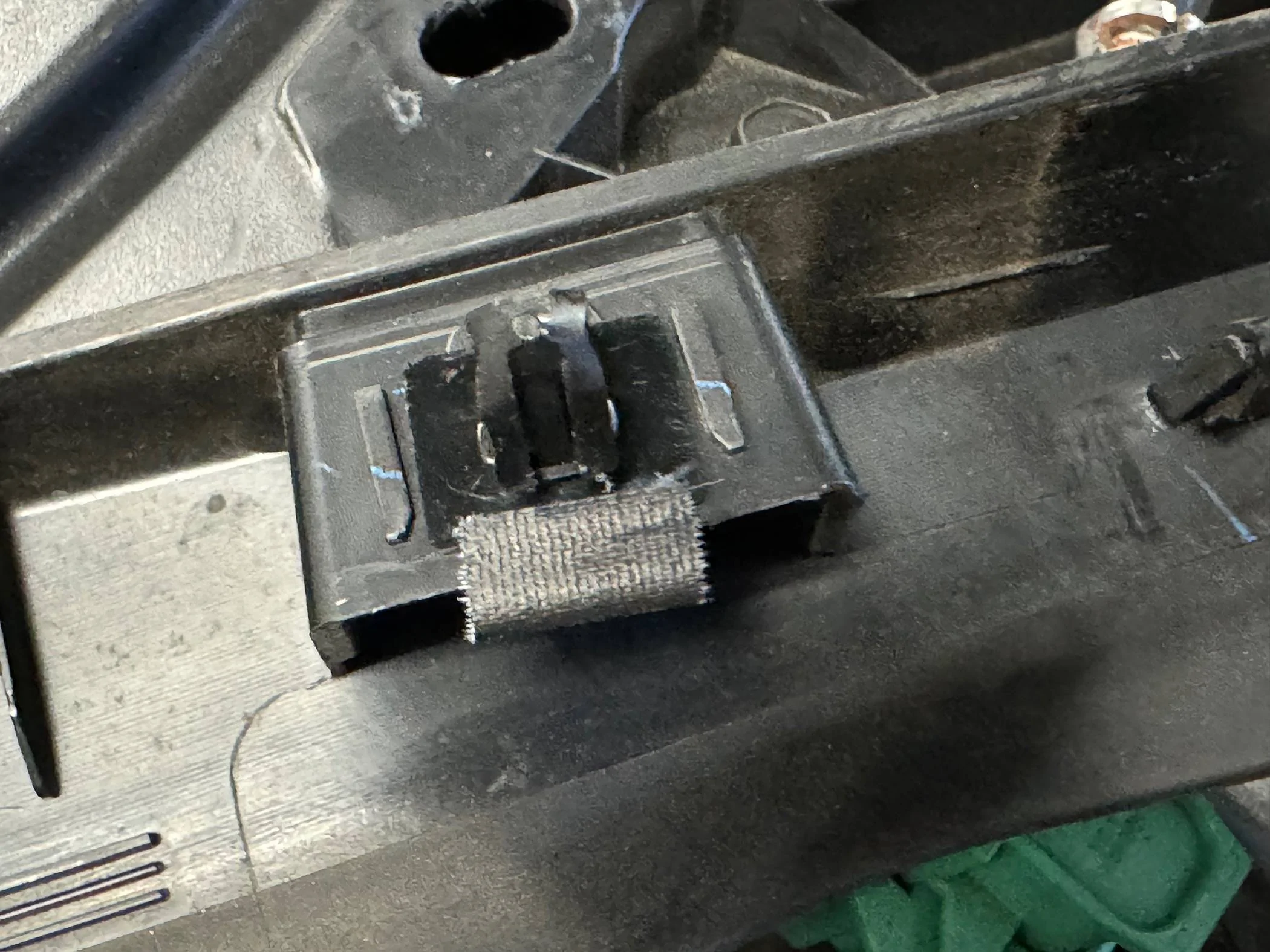
The first couple photos are not specific to this project, but I thought I’d share what I’ve done to lessen the chances of losing clips when I remove my trim panels. I’ve added small pieces of gaffer’s tape to each clip to help hold them in place. Though not perfect, I’ve found this works well to reduce clips becoming dislodged and/or lost.

Next, be very careful with your tools and components. If you drop anything to the bowels of the fenders, there’s a good chance it’ll be lost forever (or you’ll spend minutes extricating it with a flexible grabber, your wife holding a flashlight, using your phone as a viewing camera to retrieve it – don’t ask me how I know).

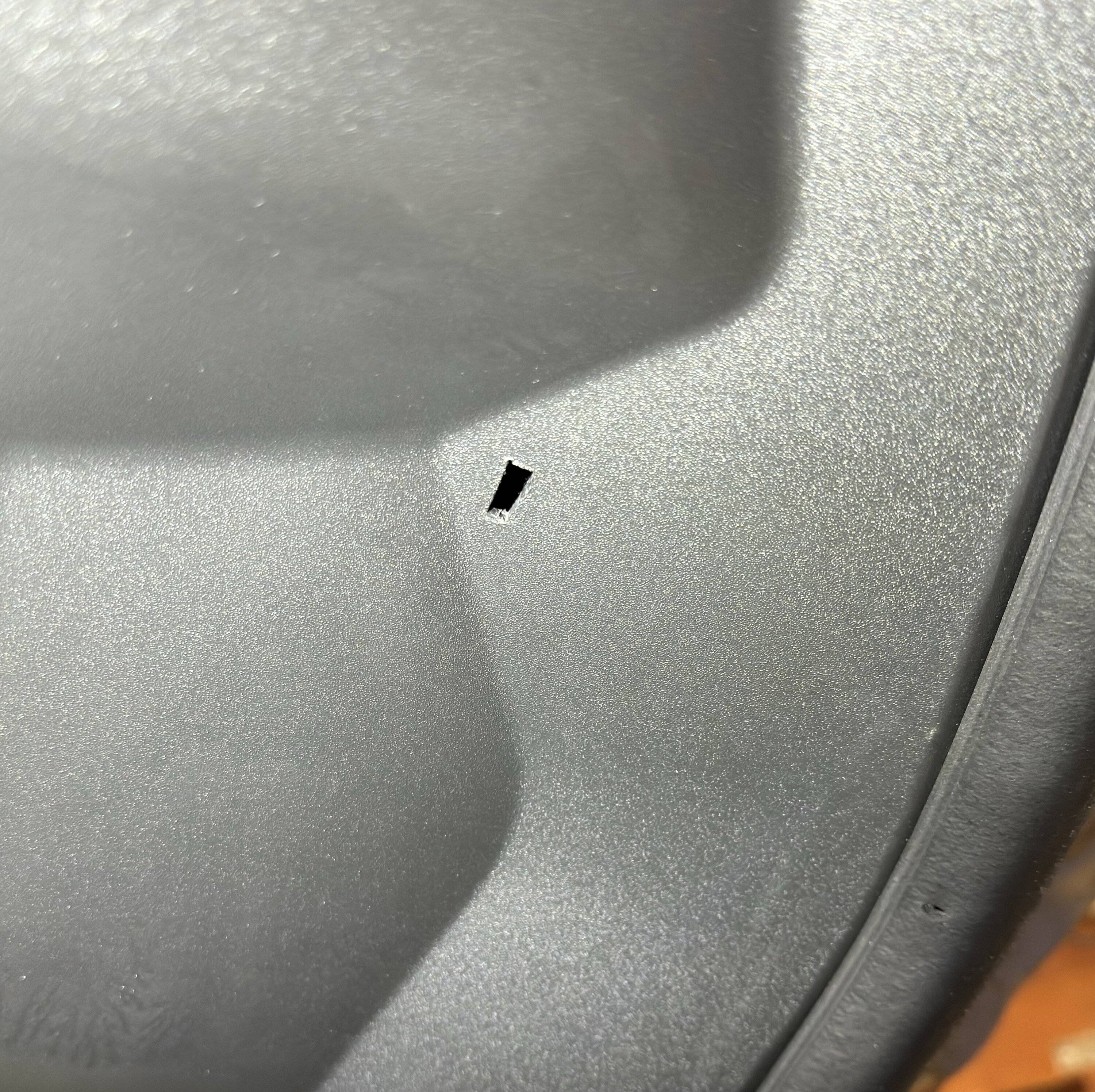
You’ll need to cut two holes in the under-hood trim – one for each of the halo lights:

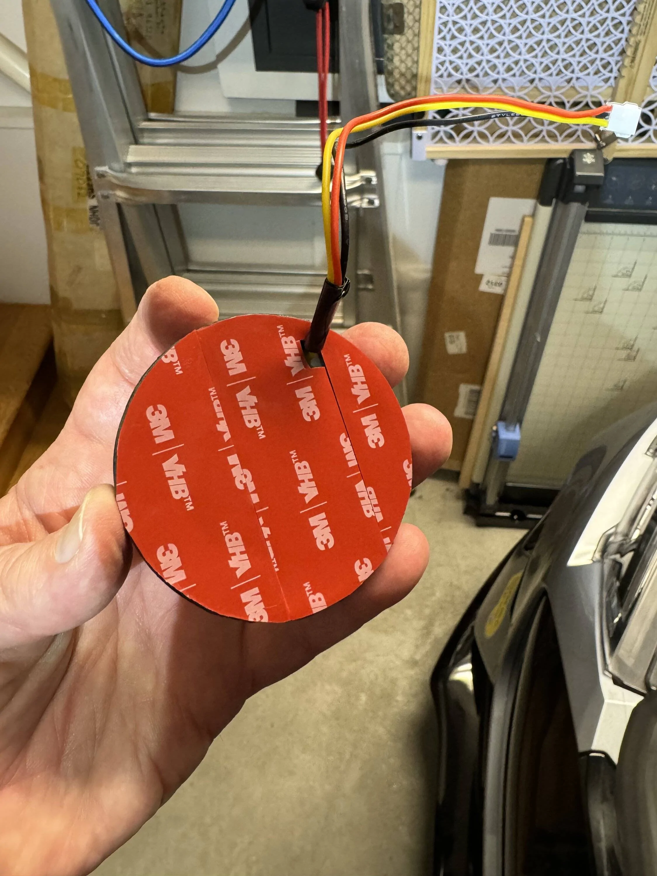
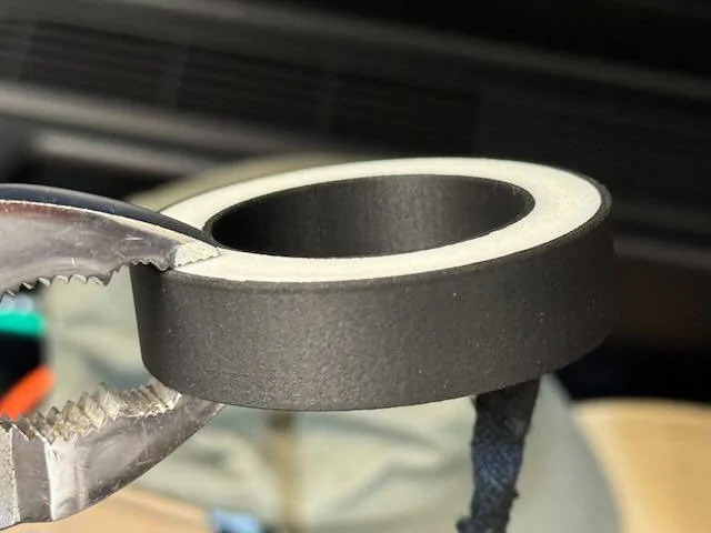
Next you’ll add double stick tape (I used 1mm thick black 3M VHB tape) to the back side of each of the Halo Light Housings.

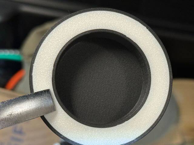
The Diffuser snaps in place. There are tiny tabs the fit into tiny slots on the Halo Housing, so be sure to line them up and then snap in the Diffuser with pliers.
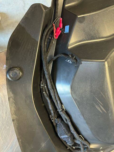
Wrap all wiring with the Wire Harness Cloth Tape to protect it (especially where it could rub against any edges such as the holes through the trim):

Wire the switch that goes next to the driver’s side Halo Light:
Run the wires to the passenger side Halo Light through the trim channel that hold the weather-seal for the frunk:
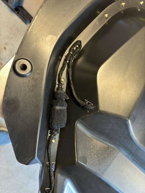
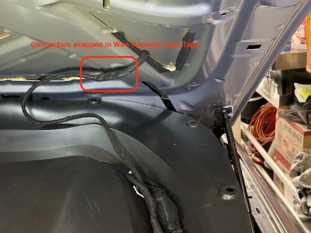
Run the wire from the switch down to the driver’s side hood hinge (leave lots of slack for future under-hood trim removals and it’s best to include a connector so that the entire trim piece can be removed if necessary). Run the cable between the hood and the supporting metal substructure, then out the hole next to the hinge pivot (wrap with lots of Wire Harness Cloth Tape around the cable and the hole itself).
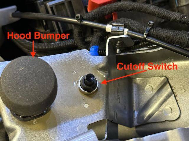
The Cutoff Switch is installed just behind the driver’s side hood bumper. There is a hole that is exactly the right size in the sheet metal for the switch. Then drill a 3/8” hole through the driver’s side trim (next to the frunk itself, not in the under-hood trim). You’ll need to do some measurements to determine exactly where to drill that hole. (I would include the measurements here but my car is in the shop for a stalled oil pump and may be there a long time.) The hole needs to allow the Cutoff Switch Activator to pass through smoothly. The Activator is installed under the trim and extends through the hole. The little tabs are to keep the Activator in place when the trim is removed.
Next install the Cutoff Switch Activator Bumper on the underside of the hood, just behind the little “shelf” the presses against the hood bumper. Make sure it presses against the Cutoff Switch Activator when the hood is closed. The easiest way to do this (once everything is wired and the lights are operational) is to put your phone in your frunk, record video, turn on the lights, and close the hood. If the light shut off, all’s well. If not, make adjustments as needed to the bumper and potentially the height of the switch itself.
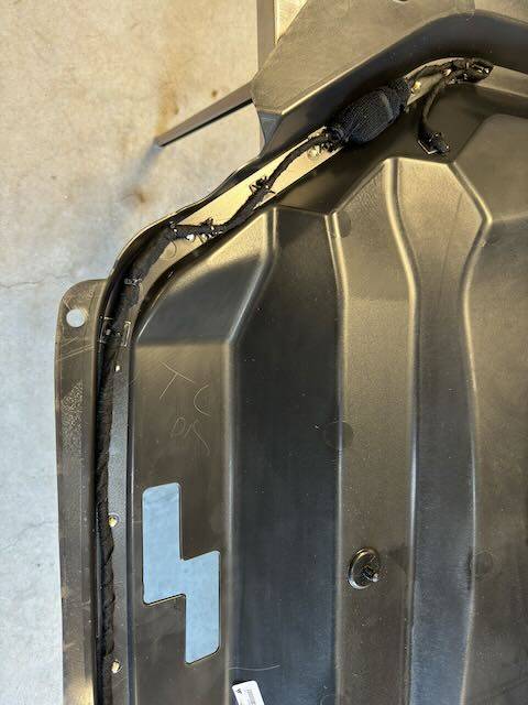
With the exception of the Cutoff Switch location, I neglected to make any photos of the wiring of the cable under the trim around the frunk. But follow the instructions at the top and it can be done without too much trouble. When running the cable up the hood hinge, make sure there’s enough slack to allow full hood movement without stretching or crimping the cable. Wrap all wires/cables in Wire Harness Cloth Tape and use lots of cable ties with mounting bases to secure the wires/cables to keep them from chafing.
That’s it – you’re done! ?
I am not a big fan of the OEM light in the frunk. Its location inside the frunk tub means that if you keep a lot of things in your frunk like I do, items close to the light can easily shadow items further away. So I decided to add lights to the underside of the hood. I chose two halo lights because I didn’t want single light sources that would cast shadows while I am digging through the stuff in my frunk. I mounted them on the diagonal part of the under-hood trim for two reasons: 1) the mounting angles provide a nice bathing of light into the frunk, and 2) that portion of the trim has space between it and the hood, thereby giving me space for cable routing.
Caution
This modification involves tapping the 12V battery, drilling/cutting multiple holes in trim pieces under the hood/around the frunk, and running wires. Access to a 3D printer (or 3D printing service) is also required. The mod isn’t difficult per se, but it is a project and if you’re not careful, things can go wrong. If you decide to try it, please know that I cannot be held responsible for anything that might happen.
TL;DR
Feel free to jump to “Solution” if you’d rather not read about the trial and error process of getting to the solution for how best to power and control the added lighting.
Attempt #1:
Some of you may recall that I posted about a lighting project for the truck. In that project I discovered that the light module I wanted to tap had three wires, one of which is the LIN bus. As I went deep into that rabbit hole I discovered that if you wanted the added lights in the trunk to go on/off when the OEM lights do, the only practical way was to modify the light module, drilling a hole through the PCB, and adding wires and a relay. It worked, but I honestly couldn’t recommend anyone else try it. (That said, to my surprise it’s been reliable for over a year – though now that I’ve put that in writing, it will likely stop working tomorrow!)
Anyway, when I started sleuthing in preparation for the frunk lighting project, I was happy to discover that the frunk light module only has two wires – obviously 12V power, and ground. “Great!” I thought, “This’ll be easy.” I thought wrong. But so confident was I that this would be easy, I make the mod-er’s cardinal sin: I completed all wiring, cable ties, etc., before testing. Dumb. When I finally tested my handiwork, I discovered that the lighting was dim and flickered, badly. Not only were the added lights dim, but even the OWM light was dim! Clearly this wasn’t good. So I quickly removed everything and went to plan B.
Attempt #2:
You’ll recall that I needed a relay for the trunk lighting, so I figured that would work here too. It didn’t. But luckily this time I didn’t commit any sins; instead I test wired everything before I finalized it all. Good thing I did. While I was getting full brightness, the flickering was terrible, made worse by the relay. It turns out that the frunk light is pulse modulated. I.e., it is not driven either on or off; instead it is constantly turned on and off to save power. So a relay wasn’t going to do a great job here either. Time to move on to plan C.
Solution:
I decided to make my added light completely independent of the existing frunk light. To do this, I needed to be able to switch the lights on and off either manually, or with the opening/closing of the hood…….or both, which is what I did. I tried to find a way to piggy back off the existing hood open signal, but couldn’t find it and I didn’t want to start taking apart more than the usual three trim panels and frunk tub. So I added a switch that is triggered by the hood closure. I call this the cutoff switch. (More below on where the switch is mounted and how it’s activated.) And since I decided I didn’t want the lights to necessarily always come on when the hood is open (or stay on if the hood needs to stay open), I added another switch in series with the cutoff switch. I call this the manual switch.
For power I tapped directly off the 12 V B+ Upfit access points. Honestly this is a bit of a PITA because the red cover over these contacts is very hard to remove and sits very tightly against the OEM cables. But it can be done – it just takes some......patience.
From P-033 Ford Police Modifier Bulletin
Once I’d tapped the 12V I connected the wire to an inline fuse block. From then it went to the Cutoff Switch and then it paired with the ground wire to go up the driver side hinge assembly and snaked up under the hood trim piece (which thankfully is not terribly difficult to remove). From there it goes to the manual switch that I installed near the driver side halo light I installed, and then to the lights themselves.
Tapping ground is much easier than the 12V since pretty much any bare metal in the car is ground. However, I decided to not try to tap the hood itself for a couple of reasons: 1) it has no electrical parts so ground is not necessarily carried reliably to the hood (it presumably wouldn’t be a design requirement), and 2) there aren’t any good tap points on the hood. Besides I had to run the power wire up from the frunk are to the hood, so running a two-wire cable wasn’t really any more difficult.
That’s it, really. Of course, doing the actual work took a lot of time and effort.
Now on to the details with photos, but first the parts lists…
Parts
(2) Halo Lights (I chose these due to their small size and the fact that they have both white and yellow lights. However the yellow is way too yellow and the white is very cold with a slight bluish tinge. I tried using both simultaneously but there was virtually no difference from just the white. That, plus the fact that it would double the current consumption, I decided to use only the white.)
18AWG Low Voltage LED Cable
(1) Cutoff (Limit) Switch
(2) Nuts for Cutoff Switch
(1) Manual Switch (comes with mounting nut)
Wire Harness Cloth Tape
Square Self-Adhesive Cable Tie Mount Bases
Cable Ties (assorted)
3D Printed Parts (The STL files for the 3D printed parts are attached in a ZIP file)
(2 each) Halo Light Housing with Diffuser (sized specifically for the above Halo Lights; if you decide to use a different light, you’ll likely need to either modify or create your own housing and diffuser)
- Housing: Bambu Black PLA-CF (though any stiff material should work)
- Diffuser: Bambu Natural PETG (I may try another filament as I’d like to come closer to color matching the OEM frunk light)
(1 each) Cutoff Switch Activator Bumper (mates with the Cutoff Switch Activator)
Detailed Photos
The first couple photos are not specific to this project, but I thought I’d share what I’ve done to lessen the chances of losing clips when I remove my trim panels. I’ve added small pieces of gaffer’s tape to each clip to help hold them in place. Though not perfect, I’ve found this works well to reduce clips becoming dislodged and/or lost.
Next, be very careful with your tools and components. If you drop anything to the bowels of the fenders, there’s a good chance it’ll be lost forever (or you’ll spend minutes extricating it with a flexible grabber, your wife holding a flashlight, using your phone as a viewing camera to retrieve it – don’t ask me how I know).
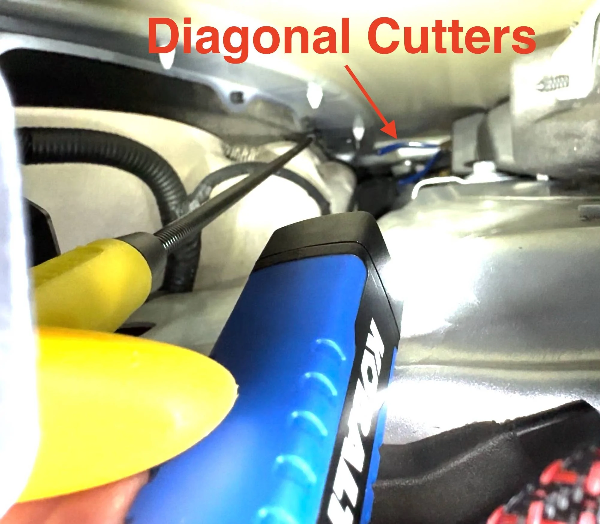
You’ll need to cut two holes in the under-hood trim – one for each of the halo lights:
Next you’ll add double stick tape (I used 1mm thick black 3M VHB tape) to the back side of each of the Halo Light Housings.
The Diffuser snaps in place. There are tiny tabs the fit into tiny slots on the Halo Housing, so be sure to line them up and then snap in the Diffuser with pliers.
Wrap all wiring with the Wire Harness Cloth Tape to protect it (especially where it could rub against any edges such as the holes through the trim):
Wire the switch that goes next to the driver’s side Halo Light:
Run the wires to the passenger side Halo Light through the trim channel that hold the weather-seal for the frunk:
Run the wire from the switch down to the driver’s side hood hinge (leave lots of slack for future under-hood trim removals and it’s best to include a connector so that the entire trim piece can be removed if necessary). Run the cable between the hood and the supporting metal substructure, then out the hole next to the hinge pivot (wrap with lots of Wire Harness Cloth Tape around the cable and the hole itself).
The Cutoff Switch is installed just behind the driver’s side hood bumper. There is a hole that is exactly the right size in the sheet metal for the switch. Then drill a 3/8” hole through the driver’s side trim (next to the frunk itself, not in the under-hood trim). You’ll need to do some measurements to determine exactly where to drill that hole. (I would include the measurements here but my car is in the shop for a stalled oil pump and may be there a long time.) The hole needs to allow the Cutoff Switch Activator to pass through smoothly. The Activator is installed under the trim and extends through the hole. The little tabs are to keep the Activator in place when the trim is removed.
Next install the Cutoff Switch Activator Bumper on the underside of the hood, just behind the little “shelf” the presses against the hood bumper. Make sure it presses against the Cutoff Switch Activator when the hood is closed. The easiest way to do this (once everything is wired and the lights are operational) is to put your phone in your frunk, record video, turn on the lights, and close the hood. If the light shut off, all’s well. If not, make adjustments as needed to the bumper and potentially the height of the switch itself.
With the exception of the Cutoff Switch location, I neglected to make any photos of the wiring of the cable under the trim around the frunk. But follow the instructions at the top and it can be done without too much trouble. When running the cable up the hood hinge, make sure there’s enough slack to allow full hood movement without stretching or crimping the cable. Wrap all wires/cables in Wire Harness Cloth Tape and use lots of cable ties with mounting bases to secure the wires/cables to keep them from chafing.
That’s it – you’re done! ?
Sponsored
Attachments
-
1.4 MB Views: 100
Last edited:
