21st Century Pony
Well-Known Member
- First Name
- Martin
- Joined
- May 21, 2022
- Threads
- 36
- Messages
- 1,976
- Reaction score
- 2,243
- Location
- Arlington, Virginia
- Vehicles
- formerly Ford Mustang Mach E 2022 Premium AWD ER, now a li'l bit of Lightning ER
- Thread starter
- #1
DIY – How to install the Ford OEM Mach E rear fog light.
WHY: to diminish or perhaps eliminate the chance of a rear-end collision in fog, in very heavy rain and in certain misty types of snowfall, or in any similar conditions of obstructed visibility on the road.
TIME TO INSTALL: this project can be done in one day or less, or it can be split into two major phases and one minor phase if time is scarce, with full functionality of the car between any phases.
Credits for helpful information go to MarkBoris for the best BCM F Connector pinout diagram, and to Su-Ch+Mache who looped in a German non-forum-member Mach E module wizard to decode the differences between BCM Europe and BCM North America software variants, which made a critical step here possible.
PARTS NEEDED, Specific:
WHAT NEEDS TO BE DONE:
NOTE: to save time and split the job into several parts, I recommend “Phase I” to be steps 1 and 2, “Phase II” to be steps 3 and 4, and “Phase III” to be steps 5 and 6. Phase I and Phase II will each suck up some time, maybe an hour or two each, while Phase III is altogether quick. Or, you can do all these steps in one day… I split the mod steps this way because you can easily use the car for days or longer with full functionality between Phase I and Phase II, and then again between Phase II and Phase III.
PHASE I – running wire inside the cabin - one to two hours.
1a. I ran the new circuit wire from the left rear corner in a “sideways Z” pattern across the car’s cabin, under the left trunk wall trim, under and behind the rear seat bottom cushion, and under the right rear and front passenger door sills. This is the Ford recommended run of additional wiring looms for the Mach E, for example the Ford (Europe) tow hitch wiring loom. I chose to sheath the wire in a corrugated flexible automotive wire channel with a split side, to avoid any chafing, from the rear left corner all the way to the right rear passenger door sill. From that point under the right C pillar there is a protected wiring channel up to almost the BCM cavity in the front passenger floor well.
1b. To remove the left cargo trunk wall trim, first pull off the rubber hatch seal from across the bottom and up the left side up to the wall trim panel’s horizontal boundary. To then remove the rear hatch threshold trim plate, unscrew the two horizontal metric bolts and the two vertical black T20 Torx bolts under the chrome ring plastic covers. Pull straight up on the black threshold plate and set aside. Pull horizontally from the top of the left wall trim plate until its clasps unclip, one by one. I recommend leaving the front of the wall plate clipped in… it’s easy to pull it all off at this point but to later get it back in all its clip holes, you’ll have to also remove the rear seat backs (not a walk in the park) and also remove the rear left door sill… too much work IMHO. As long as you can look along the white metal wall behind the left wall trim plate, you can weasel the new wire into position.
1c. Leave about two feet of the new wire coiled up and tuck it in behind the trim plate next to the several computer modules in the rear right corner… there is a hole to the bumper cavity behind the big black computer module, and you’ll need that two feet of wire for the Phase II connections outside that metal wall later.
1d. Grab the front edge of the rear seat’s bottom cushion, about where the passenger’s legs would be on either side, and yank it straight up in both places. The two vertical loop hasps will release. Then, gently pull up the rear of the seat cushion off its three metal retainer posts welded to the floor of the car. The seat cushion will now come out of the car, slipping around the seatbelt clasps. You’ll see a row of four black C shaped child seat LATCH hasps, and an inch or so behind you’ll see the seat bottom cushion vertical retainer posts (they are actually flat pieces of sheet steel, but I’ll call them “posts” here for now). Run the sheathed wire circuit from left to right in between the row of LATCH hasps and the row of the seat bottom cushion retainers… both rows of hasps will keep the new wire run in its place.
1e. Unpin and pull out the right rear and also the right front door sills. They pull straight up. Under both sills you’ll see a flat shiny plastic plate the length of each door sill. These plates are the ceilings of the wiring run channels underneath. Starting from either end, pull gently up with a small flathead screwdriver on each side clasp of the tunnel ceiling plate, and the wiring tunnel will open… it’ll be about ½ full of existing wiring. Just weasel the new circuit wire through both wiring tunnels and thru the connecting hollow space under the B Pillar. Once the wire reaches the front passenger footwell wall, you can close up both wiring tunnels, pop the door sills back on and reinsert the rear passenger seat cushion into position.
1f. To reinsert the rear seat cushion, first locate its metal-reinforced horizontal slits that’ll go over the seat cushion retainers in the back of the cushion (the row of white flat metal uprights on the floor). Slip the cushion over these three seat retainers, and then, one by one, insert the seatbelt clasps back into their seat cushion holes, bending them upright as you insert them. NOTE: if you don’t do this to each seatbelt clasp, the seat cushion will not sit flat on the floor in its designated place. Finally, once all the vertical white cushion retainers are in their place and all the seatbelt clasps are also snugged in their place, just push straight down on the two front seat latches and they’ll click-slide into their locking positions.
1g. Go back to the left rear corner and reinsert the side wall trim panel into position. First, check the two big yellow clasps… they tend to slide out of their positioning brackets and often they’ll just stay stuck in the white metal wall. Take any yellow clasp out of the white metal wall and check their correct positions in their brackets on the black plastic wall... this is important to do slowly and carefully or your car will gain weird shudders and resonances back there. Then, just push the yellow clasp areas and then all the top metal clasp areas into their locked positions. Finally, please CHECK the very bottom rear wall of the corner pocket… that part also needs to interlock with its two small T channels. If the T channels aren’t aligned, pull just that pocket part of the wall trim out and realign it until the T channels are properly interlocked (again, your car will gain weird judders etc. if this part is not interlocked correctly).
SKIP THIS LINE IF YOU WILL IMMEDIATELY GO ON TO PHASE II, or otherwise just reinsert the hatch threshold into its position, screw down the two horizontal metric bolts and the two black T20 Torx bolts, and re-hook the rubber hatch trim if you will stop the installation and just use the car for a while.
2a. Pull off the two trim plates in the front passenger foot well. The top place has two retaining push pins which come straight down, their head and then their body. That trim plate pivots straight down and then pulls back and out. The bottom trim plate then can be just yanked by either side edge, straight back. The metal clasps on this trim plate are unlikely to break.
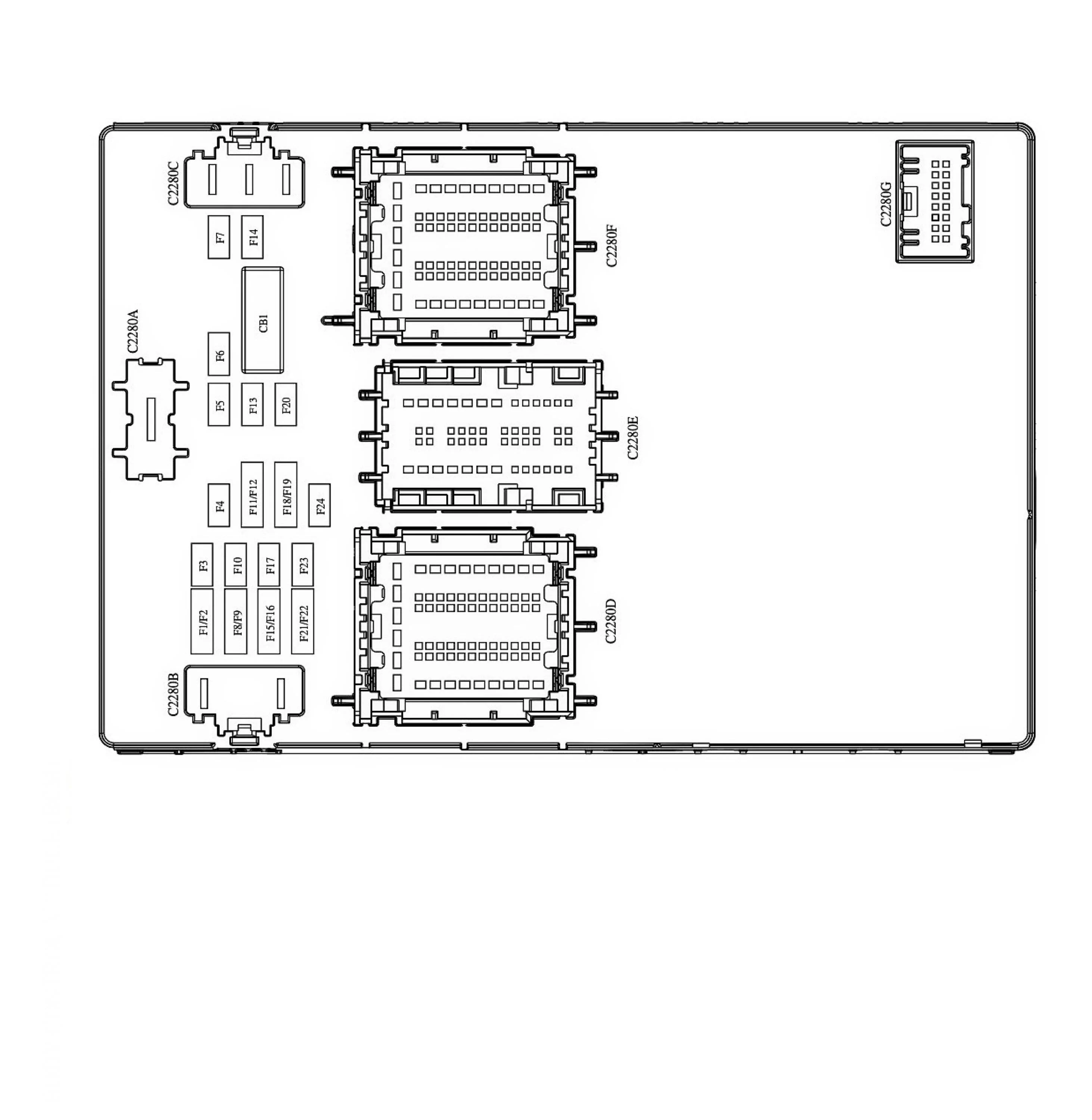
2b. The Body Control Module (BCM) is right in front of you, the big box with fuses on the left side and three big horizontal multi-pin connectors up its center. 1st, it’s a good idea and Ford-recommended to disconnect the 12V battery’s negative post before messing with the BCM. Once that is disconnected in the frunk, you’ll be disconnecting the top multi-pin connector, i.e. Connector F. See pic #3.
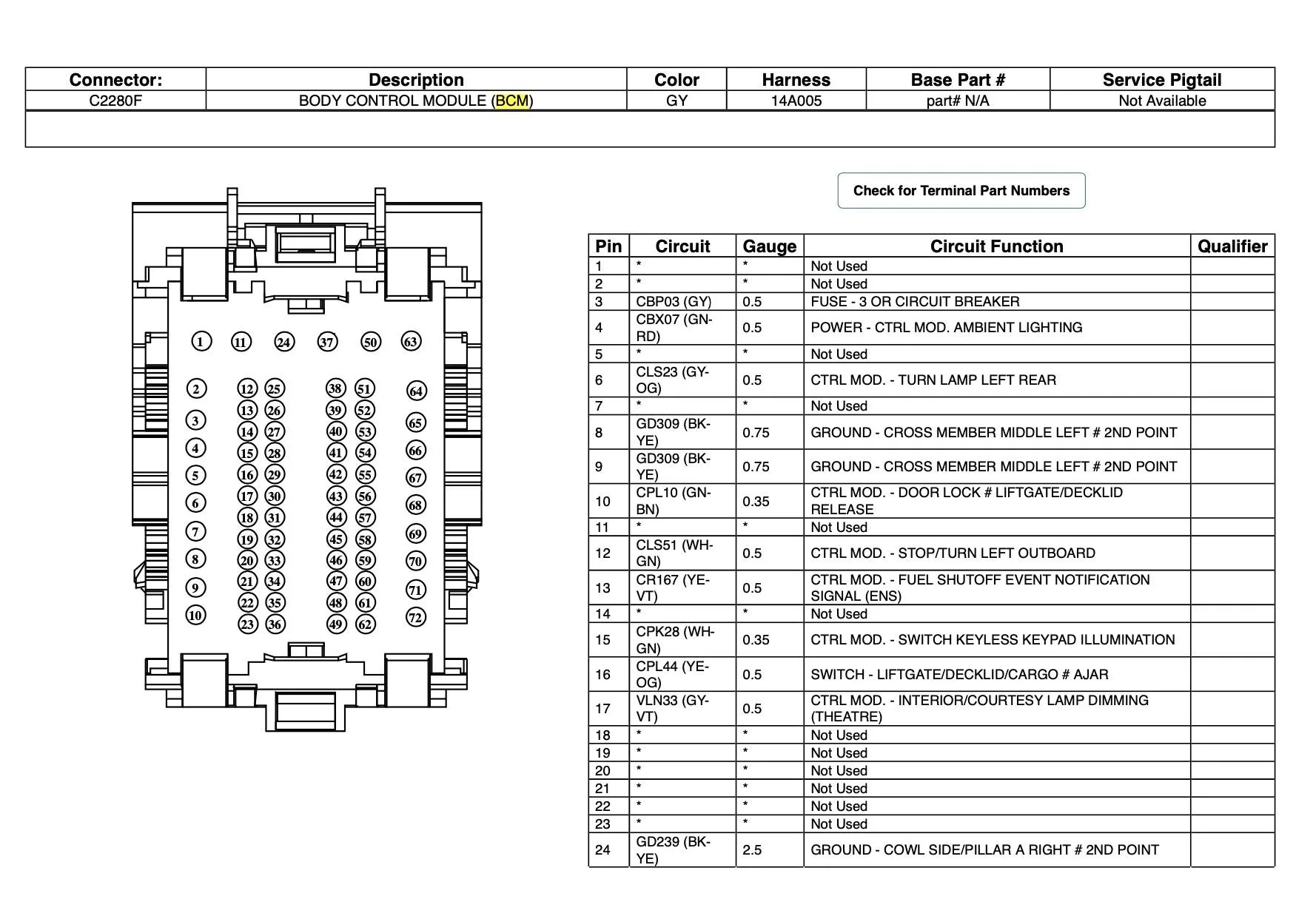
2c. To disconnect the horizontal Connector F in the top position, pivot the locking bar across its face about 90 degrees. Then, pull the F Connector straight back toward you. You’ll see several rows of female pins, with some slots empty… the corresponding male pins are in the BCM. Look at the BCM part of the F Connector and you’ll see small numbers along the pin rows. On the top row, you’ll notice pin #67 (see attached picture diagram of same). See pic #4.
2d. On the female pin side of the F Connector you just pulled off, snip off the Zip tie and then pull off the wiring cover. Look at the F Connector – on one side beneath the cover you just pulled off, there is a bunch of wires going into holes, and a bunch of empty holes as well. Locate the empty hole which corresponds to male pin #67… that’s where you’ll be inserting the Ford Motorcraft female connector from the five-pack of DU2Z-14474-DA connectors. Now flip the F Connector and notice on its black mating face plate there is a different color plastic insert running the whole length of the faceplate. This is the locking plate for all the female connectors. Take it out by pulling / wedging it out toward the front. Then once the locking plate is put, carefully orient the new Ford DU2Z-14474-DA female connector pigtail exactly as its brethren are oriented (look in their face “throats” and you’ll see little tension tongues in a row… orient the new one the same way) and just push this female connector in. It’ll gently “click”. Reinsert the locking face plate into the front, tug on the new connector to make sure it’s secure, put on the 90-degree wiring outer cover, add a Zip tie to hold it in place, and lock the F Connector back into position.
2e. Take the Posi-Lock or whatever crimp wire connector you have ready, strip and connect the new pigtail and the new circuit wire you just ran from the rear left corner. Apply heat-shrink tape. Reconnect the negative post of the 12V battery. Close up the BCM cavity with the two trim plates in the front passenger foot well. You are done with Phase I.
You can stop the project for as long as you want and use the car normally at this point until you are ready / have the time to start Phase II.
PHASE II - adding hardware inside the rear bumper - starts by removing the rear bumper cover. Altogether about two+ hours.
3A. Once you have removed the rear bumper cover, position it so the black inside faces you. Unscrew the four bolts, disconnect the two-wire plug connector and take out the North American reverse light housing. Compare the North American and the European reverse light housing. You’ll notice their lenses and their black back covers are identical... matter of fact, the North American (marked “N.A.”) part number for the reverse light and the European (marked “E.C.E”) are both embossed on the black back cover’s edge. Look inside and compare the LEDs in the inside reflector scallops and also look into both wire connector housing plugs… you’ll see they are keyed differently, for different wire loom connectors and also the North American light housing plug is molded to not accept a third wire. Once you’ve compared things, put the new Europe Reverse + rear fog light housing into position with the four bolts.
3b. Looking at the rear bumper cover from its "inside", the center wire is the ground wire. The right wire (on the two-wire plug) is the reverse light wire. Same for the new three-wire Motorcraft pigtail, which means the left pigtail wire is for the rear fog light. NOTE: on the Motorcraft three-wire pigtail, all three wires are green so it pays to know which of the two outside wires is the reverse light wire and which is the rear fog light wire, so as connect each to the correct wiring loom wires.
3c. Cut the old two-wire connector plug pigtail about 6 – 8 inches up from the plug. Connect the center (GROUND) green wire of the new three-wire Motorcraft pigtail to the blue / violet GROUND wire you just cut. Connect the right (as you look at the back of the light) green REVERSE wire to the reverse green / brown wire you just cut. Leave the left green pigtail wire loose for now.
3d. Look at the old two-wire connector plug. It has a sliding white locking plate on its top. Take the white locking plate off and emplace it on the new three-wire pigtail plug. Use a small flathead screwdriver to slightly move the outer legs of the locking plate outward, past their stop hooks, to remove the white plate (use the new three-wire plug as a guide to the locking mechanism common to both plugs). This locking plate is important, as vibration and water under the rear bumper cover is likely to dislodge the plug from the reverse light housing, sight unseen. See pic #5.
4a. Under the rear left corner of the car, locate where the main rear wiring loom goes into the car through a large hole secured by a big rubber grommet. Pull the big rubber grommet down and loose from the car’s body and then pull the extra loops of the new wire from inside thru this hole, unwind the electric tape from either end of the big rubber grommet’s wire tunnel, and weasel the new wire thru the grommet’s wiring tunnel. Re-tape the electric tape on the ends of the grommet’s wiring tunnel. Re-insert the rubber grommet into its position.
4b. THIS STEP IS THE OTHER TIME SUCK AND IT IS A LOT OF CAREFUL, DELICATE, METICULOUS WORK UNDER THE CORNER OF THE CAR… do not start it until you have the time and the right amount of patience. Just this step, on both halves of the big rear bumper multi-pin connector, took me a good hour although I was working very methodically. Look at both halves of the big multi-point connector right under the rubber grommet on the outside of the car. One half will have female Motorcraft connector pins, and the other half will have the corresponding male pins. There will also be many empty pin holes on both halves. Just like in Step 2d. above in Phase I, you need to snip the securing Zip tie, take off the outer 90-degree wiring cover, identify which hole to use for the new rear fog light circuit (unlike on the BCM, here it doesn’t matter which hole set you pick as long as you pick the same male and female hole, so that the new pins will mate). On this multi-pin connector, because of its location outside the car’s cabin, there are additional soft silicone weather-proofing seals on each half, on the backs where the wires go in… one is green and one is light red. Snuggle each of these silicone weather seals out and back along their wires with a very small diameter screwdriver at least one inch, far enough to be able to insert a new connector pigtail, male and female, into their chosen holes. Wiggle out the locking plates on the front of each half, orient the female and also the male pin so they match their neighbors’ orientation, insert the female and the male pin into their positions and then bend back and snake the new pins’ pigtail wires thru the corresponding holes in the silicone seals, and then insert the two front pin locking plates. Push the silicone weather seals back into position, put on the 90-degree wiring covers and secure both with Zip-ties. Again, you’ll have to do everything twice, once on each half of this connector.
4c. Connect the new circuit wire you just pulled thru the big rubber grommet to the new pigtail on the male half of the big multi-pin connector (Posi-Lock or a crimp tube). Cut off excess wire. Seal with heat-shrink tubing.
4d. On the rear bumper, connect the new reverse + rear fog light pigtail to the remainder of the new wire (Posi-Lock or a crimp tube). Seal with heat-shrink tubing.
4e. Run the new wire circuit along the rear bumper cover’s existing wiring loom. Secure with Zip-ties. Connect the new wire to the new female pigtail of the big multi-pin connector. Seal with heat-shrink tubing.
4f. Reassemble the rear bumper cover onto the bumper. Reconnect the big multi-pin rear bumper connector as well as the two rear wheel side fender LED position lights on either side.
Note: again, if you run out of time or patience, this is a good time to stop for as long as you deem it necessary. Otherwise, Phase III is easy and short in time and effort.
PHASE III adding and activating controls - should be done in 15 – 20 minutes.
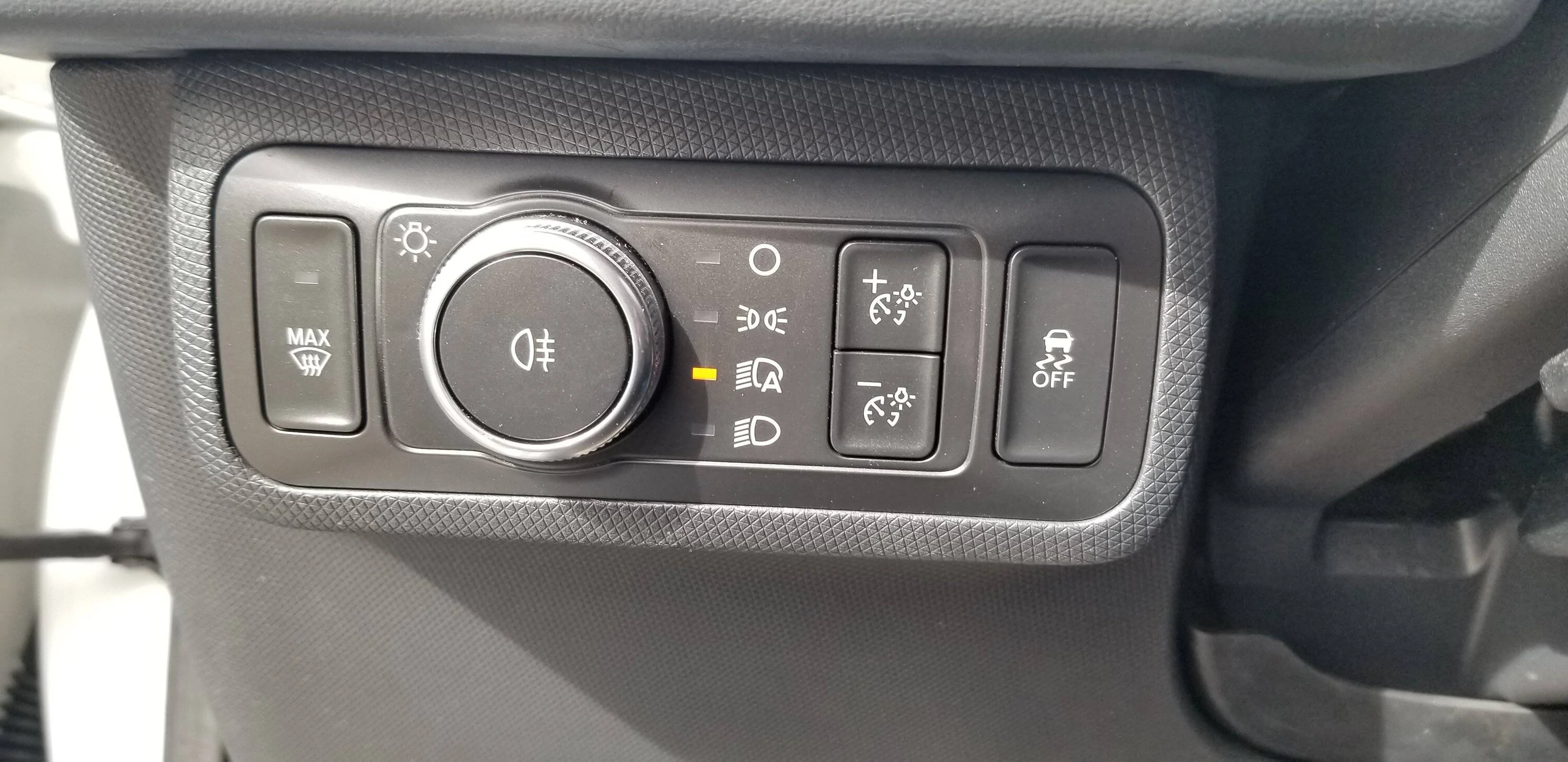
5a. The headlight switch has two parts – the body and the cover. You can gently pull off the cover by levering it up with a trim tool until it releases… it has eight small plastic retainer hasps, four on top edge and four on bottom edge. Matter of fact, the North America and the Europe covers for the headlight switch are identical in shape and in markings.
5b. Once the switch cover is off, the four retainer detents for the switch are at the 12, 3, 6 and 9 o’clock positions. A narrow trim tool or a narrow flat head screwdriver, inserted at either 3 or 9 o’clock, will release that side… then the headlight switch just eases out.
5c. Move the lights wiring harness plug from the North America switch to the Europe switch and push the new Europe switch into its position. Replace the old switch’s front cover… just gently push it in onto the now-spare switch. That’s it … no more wires to run.
6a. Fire up Forscan. I use version 2.3.54 now.
6b. Choose the BCM “AS BUILT” script sequence. Reason: although this Forscan version now has the “click-& choose” script for the BCM as well as the AS BUILT script for the BCM, I found the “click-&-choose” script was not fully functional for this modification… it adjusted only one parameter, of two parameters needed. So, you might as well run the AS BUILT script to adjust both parameters.
6c. In Forscan, in the BCM AS BUILT script,
on line 726-11-04, change
xxxx-x0xx-xx to
xxxx-x1xx-xx
on line 726=12-02, change
xxxx-xxxx-x7 to
xxxx-xxxx-xF
“Write” the changes. Your rear fog light mod is complete.
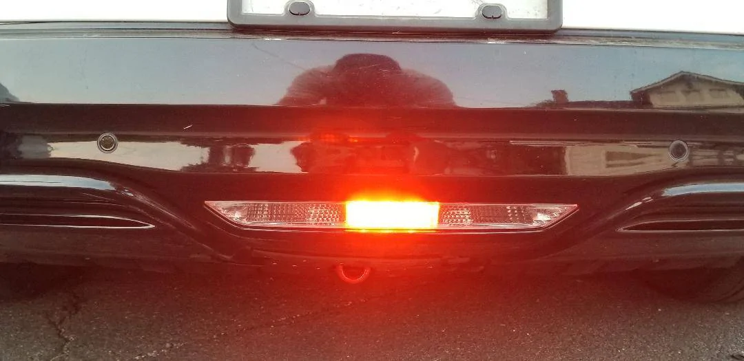
TO TEST: if it is daylight, put the headlight switch in LIGHTS ON (bottom setting). Push the rear fog button. The orange rear fog telltale should light up on the IPC. Leave the PAAK / fob in the car and step behind it. The center of the reverse light should be lit bright red. See attached pix.
If it is night, leave in LIGHTS AUTO. Push the rear fog button. See above.
Note: it took my BCM a short drive to digest everything and let the rear fog light work… if your new rear fog light doesn’t immediately work, I suggest a short drive and then a re-test.


WHY: to diminish or perhaps eliminate the chance of a rear-end collision in fog, in very heavy rain and in certain misty types of snowfall, or in any similar conditions of obstructed visibility on the road.
TIME TO INSTALL: this project can be done in one day or less, or it can be split into two major phases and one minor phase if time is scarce, with full functionality of the car between any phases.
Credits for helpful information go to MarkBoris for the best BCM F Connector pinout diagram, and to Su-Ch+Mache who looped in a German non-forum-member Mach E module wizard to decode the differences between BCM Europe and BCM North America software variants, which made a critical step here possible.
PARTS NEEDED, Specific:
- One Ford OEM Mach E headlight switch, Europe version, with a rear fog light on / off push button inside the round silver light selector bezel. Part # LK9T-13D061-BBW (as opposed to the North American headlight switch part #, LK9T-13D061-ABW). Cost was about $218 in September 2022, + shipping. See attached picture #1.
- One Ford OEM reverse + rear fog light combination light housing. Part # LJ8B-15500 – B. Note: this part number is almost identical to the part # for the Ford OEM reverse light housing for North America, LJ8B-15500 – A except for the last letter. The Ford Europe reverse + fog light housing has six white LEDs and its middle LED is a very strong red LED, while the North America light housing has seven white LEDs and no red LED. Moreover, the Ford Europe reverse + rear fog light housing has three wires in its connector, while the North America light housing has only two wires and is made to not accept a third wire. Cost in September 2022 was about $158 + shipping.
- One Ford Motorcraft specialized three-wire pigtail with a keyed plug connector that fits the Ford Europe reverse light housing. The North American plug connector is keyed differently and will not plug into the Ford Europe reverse + rear fog light housing, and vice versa. Part # is “2021 Ford Mustang Mach-E Back Up Lamp Connector Motorcraft 12258GM“ as listed on Ebay. Cost: $53, shipped from Connecticut. Sold by Autopartsgeek on Ebay. See pic #2.
- One 25-foot spool of automotive 20-gauge stranded wire, to run a new circuit from the BCM to the new reverse + rear fog light housing. Remember the new three-wire pigtail mentioned above?
- One 5-pack (actually, two (2) individual connectors but the packs come with five) of Ford Motorcraft female connectors. Part # DU2Z-14474-DA. Cost is about $25 and I bought mine from a Ford dealership parts counter… you can use FordPass points.
- One (1) Ford Motorcraft male connector pigtail to mate with the female Motorcraft connectors above. I sniveled and a friendly Ford dealership service tech threw me one, hence no part #.
- Six Posi-Lock wire connectors. Alternately, you can use six aluminum crimp tubes for 18 – 20 gauge automotive wire.
- Six pieces of heat-shrink tubing. The rear of the Mach E inside the rear bumper cover, especially for cars with a tow hitch installed, gets a lot of moisture and water thrown in there in bad weather because of the bumper cover’s underbody cutout for the hitch (guess how I know this? He hee) so moisture sealing of these wire connections is recommended.
- A dozen feet of the flexible corrugated wire protective sheath to protect the new wire circuit as you run it the length of the cabin and out to the rear bumper. Sold at any automotive supply store.
WHAT NEEDS TO BE DONE:
- Run the new wire circuit from the BCM all the way to the rear bumper’s reverse light location, through three (3) Ford Motorcraft multi-pin connector housings.
- Connect the new rear fog light circuit to the BCM’s pin #67 in the top (“F”) BCM multi-pin connector.
- Swap out the North American reverse light housing for the Ford Europe reverse + rear fog light housing.
- Add the new Ford Motorcraft three-wire pin to the two old wires and the one new wire at the reverse + rear fog light housing in the rear bumper cover.
- Swap out the old headlight switch for the new Ford Europe headlight switch (this step is very very easy). No new wire circuit to run here from the new switch and under the dashboard… these now all work thru CANBUS signals.
- Change two digits in two separate lines of code in the BCM, via Forscan.
NOTE: to save time and split the job into several parts, I recommend “Phase I” to be steps 1 and 2, “Phase II” to be steps 3 and 4, and “Phase III” to be steps 5 and 6. Phase I and Phase II will each suck up some time, maybe an hour or two each, while Phase III is altogether quick. Or, you can do all these steps in one day… I split the mod steps this way because you can easily use the car for days or longer with full functionality between Phase I and Phase II, and then again between Phase II and Phase III.
PHASE I – running wire inside the cabin - one to two hours.
1a. I ran the new circuit wire from the left rear corner in a “sideways Z” pattern across the car’s cabin, under the left trunk wall trim, under and behind the rear seat bottom cushion, and under the right rear and front passenger door sills. This is the Ford recommended run of additional wiring looms for the Mach E, for example the Ford (Europe) tow hitch wiring loom. I chose to sheath the wire in a corrugated flexible automotive wire channel with a split side, to avoid any chafing, from the rear left corner all the way to the right rear passenger door sill. From that point under the right C pillar there is a protected wiring channel up to almost the BCM cavity in the front passenger floor well.
1b. To remove the left cargo trunk wall trim, first pull off the rubber hatch seal from across the bottom and up the left side up to the wall trim panel’s horizontal boundary. To then remove the rear hatch threshold trim plate, unscrew the two horizontal metric bolts and the two vertical black T20 Torx bolts under the chrome ring plastic covers. Pull straight up on the black threshold plate and set aside. Pull horizontally from the top of the left wall trim plate until its clasps unclip, one by one. I recommend leaving the front of the wall plate clipped in… it’s easy to pull it all off at this point but to later get it back in all its clip holes, you’ll have to also remove the rear seat backs (not a walk in the park) and also remove the rear left door sill… too much work IMHO. As long as you can look along the white metal wall behind the left wall trim plate, you can weasel the new wire into position.
1c. Leave about two feet of the new wire coiled up and tuck it in behind the trim plate next to the several computer modules in the rear right corner… there is a hole to the bumper cavity behind the big black computer module, and you’ll need that two feet of wire for the Phase II connections outside that metal wall later.
1d. Grab the front edge of the rear seat’s bottom cushion, about where the passenger’s legs would be on either side, and yank it straight up in both places. The two vertical loop hasps will release. Then, gently pull up the rear of the seat cushion off its three metal retainer posts welded to the floor of the car. The seat cushion will now come out of the car, slipping around the seatbelt clasps. You’ll see a row of four black C shaped child seat LATCH hasps, and an inch or so behind you’ll see the seat bottom cushion vertical retainer posts (they are actually flat pieces of sheet steel, but I’ll call them “posts” here for now). Run the sheathed wire circuit from left to right in between the row of LATCH hasps and the row of the seat bottom cushion retainers… both rows of hasps will keep the new wire run in its place.
1e. Unpin and pull out the right rear and also the right front door sills. They pull straight up. Under both sills you’ll see a flat shiny plastic plate the length of each door sill. These plates are the ceilings of the wiring run channels underneath. Starting from either end, pull gently up with a small flathead screwdriver on each side clasp of the tunnel ceiling plate, and the wiring tunnel will open… it’ll be about ½ full of existing wiring. Just weasel the new circuit wire through both wiring tunnels and thru the connecting hollow space under the B Pillar. Once the wire reaches the front passenger footwell wall, you can close up both wiring tunnels, pop the door sills back on and reinsert the rear passenger seat cushion into position.
1f. To reinsert the rear seat cushion, first locate its metal-reinforced horizontal slits that’ll go over the seat cushion retainers in the back of the cushion (the row of white flat metal uprights on the floor). Slip the cushion over these three seat retainers, and then, one by one, insert the seatbelt clasps back into their seat cushion holes, bending them upright as you insert them. NOTE: if you don’t do this to each seatbelt clasp, the seat cushion will not sit flat on the floor in its designated place. Finally, once all the vertical white cushion retainers are in their place and all the seatbelt clasps are also snugged in their place, just push straight down on the two front seat latches and they’ll click-slide into their locking positions.
1g. Go back to the left rear corner and reinsert the side wall trim panel into position. First, check the two big yellow clasps… they tend to slide out of their positioning brackets and often they’ll just stay stuck in the white metal wall. Take any yellow clasp out of the white metal wall and check their correct positions in their brackets on the black plastic wall... this is important to do slowly and carefully or your car will gain weird shudders and resonances back there. Then, just push the yellow clasp areas and then all the top metal clasp areas into their locked positions. Finally, please CHECK the very bottom rear wall of the corner pocket… that part also needs to interlock with its two small T channels. If the T channels aren’t aligned, pull just that pocket part of the wall trim out and realign it until the T channels are properly interlocked (again, your car will gain weird judders etc. if this part is not interlocked correctly).
SKIP THIS LINE IF YOU WILL IMMEDIATELY GO ON TO PHASE II, or otherwise just reinsert the hatch threshold into its position, screw down the two horizontal metric bolts and the two black T20 Torx bolts, and re-hook the rubber hatch trim if you will stop the installation and just use the car for a while.
2a. Pull off the two trim plates in the front passenger foot well. The top place has two retaining push pins which come straight down, their head and then their body. That trim plate pivots straight down and then pulls back and out. The bottom trim plate then can be just yanked by either side edge, straight back. The metal clasps on this trim plate are unlikely to break.
2b. The Body Control Module (BCM) is right in front of you, the big box with fuses on the left side and three big horizontal multi-pin connectors up its center. 1st, it’s a good idea and Ford-recommended to disconnect the 12V battery’s negative post before messing with the BCM. Once that is disconnected in the frunk, you’ll be disconnecting the top multi-pin connector, i.e. Connector F. See pic #3.
2c. To disconnect the horizontal Connector F in the top position, pivot the locking bar across its face about 90 degrees. Then, pull the F Connector straight back toward you. You’ll see several rows of female pins, with some slots empty… the corresponding male pins are in the BCM. Look at the BCM part of the F Connector and you’ll see small numbers along the pin rows. On the top row, you’ll notice pin #67 (see attached picture diagram of same). See pic #4.
2d. On the female pin side of the F Connector you just pulled off, snip off the Zip tie and then pull off the wiring cover. Look at the F Connector – on one side beneath the cover you just pulled off, there is a bunch of wires going into holes, and a bunch of empty holes as well. Locate the empty hole which corresponds to male pin #67… that’s where you’ll be inserting the Ford Motorcraft female connector from the five-pack of DU2Z-14474-DA connectors. Now flip the F Connector and notice on its black mating face plate there is a different color plastic insert running the whole length of the faceplate. This is the locking plate for all the female connectors. Take it out by pulling / wedging it out toward the front. Then once the locking plate is put, carefully orient the new Ford DU2Z-14474-DA female connector pigtail exactly as its brethren are oriented (look in their face “throats” and you’ll see little tension tongues in a row… orient the new one the same way) and just push this female connector in. It’ll gently “click”. Reinsert the locking face plate into the front, tug on the new connector to make sure it’s secure, put on the 90-degree wiring outer cover, add a Zip tie to hold it in place, and lock the F Connector back into position.
2e. Take the Posi-Lock or whatever crimp wire connector you have ready, strip and connect the new pigtail and the new circuit wire you just ran from the rear left corner. Apply heat-shrink tape. Reconnect the negative post of the 12V battery. Close up the BCM cavity with the two trim plates in the front passenger foot well. You are done with Phase I.
You can stop the project for as long as you want and use the car normally at this point until you are ready / have the time to start Phase II.
PHASE II - adding hardware inside the rear bumper - starts by removing the rear bumper cover. Altogether about two+ hours.
3A. Once you have removed the rear bumper cover, position it so the black inside faces you. Unscrew the four bolts, disconnect the two-wire plug connector and take out the North American reverse light housing. Compare the North American and the European reverse light housing. You’ll notice their lenses and their black back covers are identical... matter of fact, the North American (marked “N.A.”) part number for the reverse light and the European (marked “E.C.E”) are both embossed on the black back cover’s edge. Look inside and compare the LEDs in the inside reflector scallops and also look into both wire connector housing plugs… you’ll see they are keyed differently, for different wire loom connectors and also the North American light housing plug is molded to not accept a third wire. Once you’ve compared things, put the new Europe Reverse + rear fog light housing into position with the four bolts.
3b. Looking at the rear bumper cover from its "inside", the center wire is the ground wire. The right wire (on the two-wire plug) is the reverse light wire. Same for the new three-wire Motorcraft pigtail, which means the left pigtail wire is for the rear fog light. NOTE: on the Motorcraft three-wire pigtail, all three wires are green so it pays to know which of the two outside wires is the reverse light wire and which is the rear fog light wire, so as connect each to the correct wiring loom wires.
3c. Cut the old two-wire connector plug pigtail about 6 – 8 inches up from the plug. Connect the center (GROUND) green wire of the new three-wire Motorcraft pigtail to the blue / violet GROUND wire you just cut. Connect the right (as you look at the back of the light) green REVERSE wire to the reverse green / brown wire you just cut. Leave the left green pigtail wire loose for now.
3d. Look at the old two-wire connector plug. It has a sliding white locking plate on its top. Take the white locking plate off and emplace it on the new three-wire pigtail plug. Use a small flathead screwdriver to slightly move the outer legs of the locking plate outward, past their stop hooks, to remove the white plate (use the new three-wire plug as a guide to the locking mechanism common to both plugs). This locking plate is important, as vibration and water under the rear bumper cover is likely to dislodge the plug from the reverse light housing, sight unseen. See pic #5.
4a. Under the rear left corner of the car, locate where the main rear wiring loom goes into the car through a large hole secured by a big rubber grommet. Pull the big rubber grommet down and loose from the car’s body and then pull the extra loops of the new wire from inside thru this hole, unwind the electric tape from either end of the big rubber grommet’s wire tunnel, and weasel the new wire thru the grommet’s wiring tunnel. Re-tape the electric tape on the ends of the grommet’s wiring tunnel. Re-insert the rubber grommet into its position.
4b. THIS STEP IS THE OTHER TIME SUCK AND IT IS A LOT OF CAREFUL, DELICATE, METICULOUS WORK UNDER THE CORNER OF THE CAR… do not start it until you have the time and the right amount of patience. Just this step, on both halves of the big rear bumper multi-pin connector, took me a good hour although I was working very methodically. Look at both halves of the big multi-point connector right under the rubber grommet on the outside of the car. One half will have female Motorcraft connector pins, and the other half will have the corresponding male pins. There will also be many empty pin holes on both halves. Just like in Step 2d. above in Phase I, you need to snip the securing Zip tie, take off the outer 90-degree wiring cover, identify which hole to use for the new rear fog light circuit (unlike on the BCM, here it doesn’t matter which hole set you pick as long as you pick the same male and female hole, so that the new pins will mate). On this multi-pin connector, because of its location outside the car’s cabin, there are additional soft silicone weather-proofing seals on each half, on the backs where the wires go in… one is green and one is light red. Snuggle each of these silicone weather seals out and back along their wires with a very small diameter screwdriver at least one inch, far enough to be able to insert a new connector pigtail, male and female, into their chosen holes. Wiggle out the locking plates on the front of each half, orient the female and also the male pin so they match their neighbors’ orientation, insert the female and the male pin into their positions and then bend back and snake the new pins’ pigtail wires thru the corresponding holes in the silicone seals, and then insert the two front pin locking plates. Push the silicone weather seals back into position, put on the 90-degree wiring covers and secure both with Zip-ties. Again, you’ll have to do everything twice, once on each half of this connector.
4c. Connect the new circuit wire you just pulled thru the big rubber grommet to the new pigtail on the male half of the big multi-pin connector (Posi-Lock or a crimp tube). Cut off excess wire. Seal with heat-shrink tubing.
4d. On the rear bumper, connect the new reverse + rear fog light pigtail to the remainder of the new wire (Posi-Lock or a crimp tube). Seal with heat-shrink tubing.
4e. Run the new wire circuit along the rear bumper cover’s existing wiring loom. Secure with Zip-ties. Connect the new wire to the new female pigtail of the big multi-pin connector. Seal with heat-shrink tubing.
4f. Reassemble the rear bumper cover onto the bumper. Reconnect the big multi-pin rear bumper connector as well as the two rear wheel side fender LED position lights on either side.
Note: again, if you run out of time or patience, this is a good time to stop for as long as you deem it necessary. Otherwise, Phase III is easy and short in time and effort.
PHASE III adding and activating controls - should be done in 15 – 20 minutes.
5a. The headlight switch has two parts – the body and the cover. You can gently pull off the cover by levering it up with a trim tool until it releases… it has eight small plastic retainer hasps, four on top edge and four on bottom edge. Matter of fact, the North America and the Europe covers for the headlight switch are identical in shape and in markings.
5b. Once the switch cover is off, the four retainer detents for the switch are at the 12, 3, 6 and 9 o’clock positions. A narrow trim tool or a narrow flat head screwdriver, inserted at either 3 or 9 o’clock, will release that side… then the headlight switch just eases out.
5c. Move the lights wiring harness plug from the North America switch to the Europe switch and push the new Europe switch into its position. Replace the old switch’s front cover… just gently push it in onto the now-spare switch. That’s it … no more wires to run.
6a. Fire up Forscan. I use version 2.3.54 now.
6b. Choose the BCM “AS BUILT” script sequence. Reason: although this Forscan version now has the “click-& choose” script for the BCM as well as the AS BUILT script for the BCM, I found the “click-&-choose” script was not fully functional for this modification… it adjusted only one parameter, of two parameters needed. So, you might as well run the AS BUILT script to adjust both parameters.
6c. In Forscan, in the BCM AS BUILT script,
on line 726-11-04, change
xxxx-x0xx-xx to
xxxx-x1xx-xx
on line 726=12-02, change
xxxx-xxxx-x7 to
xxxx-xxxx-xF
“Write” the changes. Your rear fog light mod is complete.
TO TEST: if it is daylight, put the headlight switch in LIGHTS ON (bottom setting). Push the rear fog button. The orange rear fog telltale should light up on the IPC. Leave the PAAK / fob in the car and step behind it. The center of the reverse light should be lit bright red. See attached pix.
If it is night, leave in LIGHTS AUTO. Push the rear fog button. See above.
Note: it took my BCM a short drive to digest everything and let the rear fog light work… if your new rear fog light doesn’t immediately work, I suggest a short drive and then a re-test.


Sponsored
Last edited: