JohnFoxeSheets
Well-Known Member
- First Name
- John
- Joined
- Jan 29, 2022
- Threads
- 28
- Messages
- 3,415
- Reaction score
- 5,514
- Location
- San Francisco
- Website
- johnfoxesheets.com
- Vehicles
- 2022 Iced Blue Silver Mach E GT
- Occupation
- Retired Engineer
- Thread starter
- #1
@MyLittlePony2022 made a modification to his MME, adding strip LED lighting to his cargo area. He wired the LED strips to the power and ground of the C489 connector (for the side lamp module in the cargo area), and since the power to that module is always on (until the car times out), he added a physical switch to enable his added lighting to be turned on or off.
I decided to see if it is feasible to use the OEM lamp module to trigger a solid-state relay to turn on/off the added LED strips. (My initial idea actually was to try to use the third wire to C489 (Switch – Overhead Console # External Control) to trigger the relay, but I discovered that in fact that wire is the LIN bus to the module and so it cannot be used as a trigger. So I instead needed to do surgery on the OEM lamp module to extract a suitable trigger.
Before we go further, I want to stress that I do not recommend others do this mod! It is time consuming, could easily end up trashing your lamp module, and if things really go south it might even damage your BCM (which would be certifiably bad). If you decide to proceed, you’re on your own. I cannot be responsible for any issues that arise should you attempt this mod.
OK, enough of the backstory and warnings, here’s what I did.
To summarize, we have three input pins on C489 (the connector to the OEM lamp module):

Courtesy @MyLittlePony2022
Pin 2 is the LIN bus and is not used (directly) for this project. Instead, we tap inside the lamp module to obtain the appropriate signal to use with our solid-state relay.
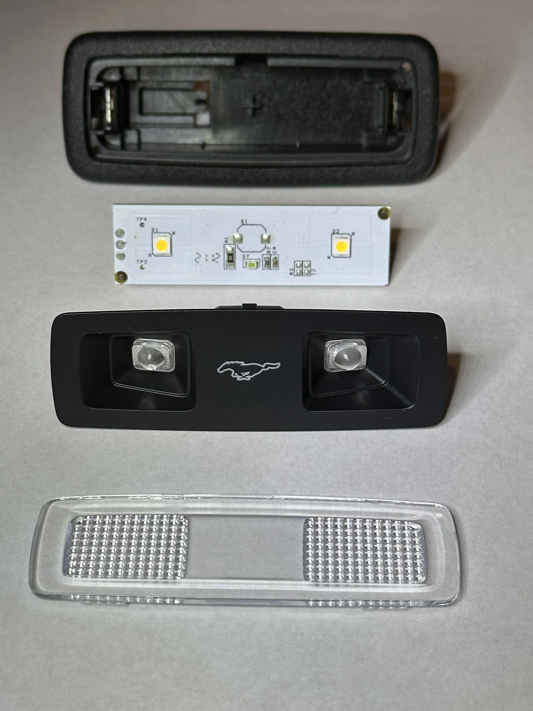
To open the module, you’ll need to remove the clear diffuser plastic by carefully prying it open from behind. There are small tabs that hold it in place and those tabs can be pushed out from behind. Once the diffuser is off, the lens assembly drops out (tapping the module onto its face helps), and then the PCB assembly can be gently pried out. It is simply press-fit in the module housing, so there’s little worry of damaging it if you’re careful.
Here is the disassembled module:

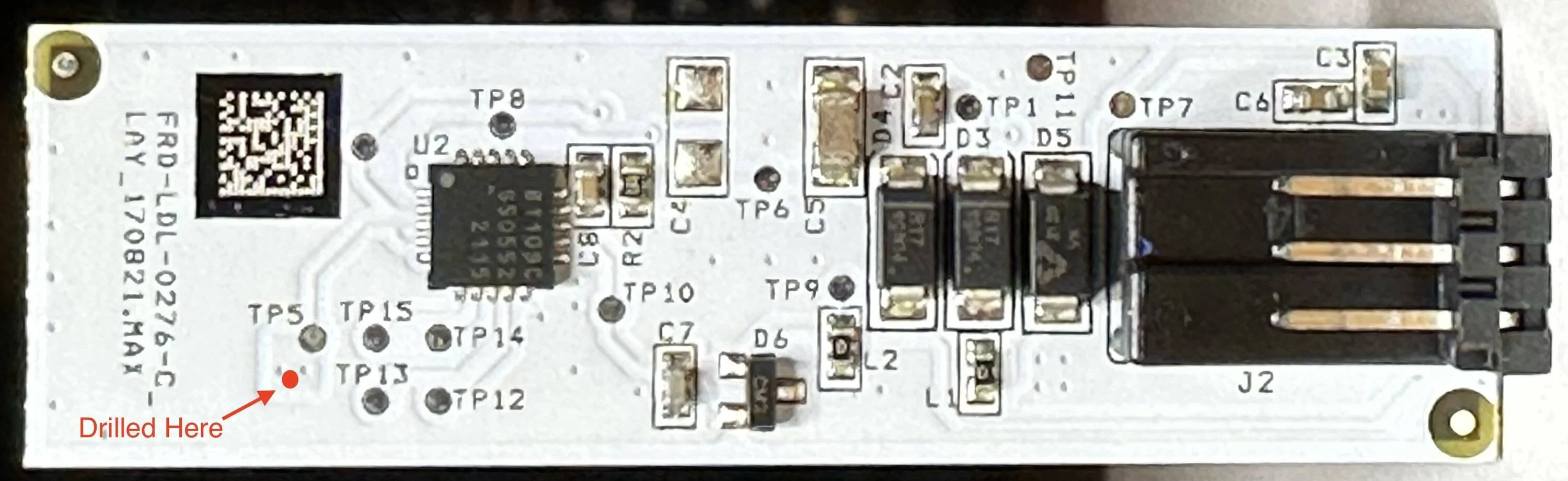
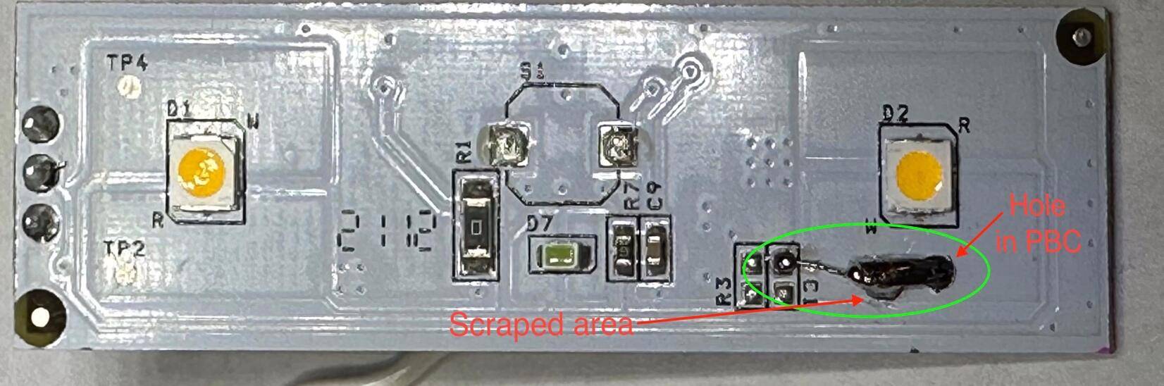
After much testing and basically trashing my lamp module, I determined that Test Point 5 (TP5) is the correct net (signal in a circuit) to drive the SS relay. Tapping that test point directly is not recommended because unless you can protect against all strain to the tap wire, there is a very high probability that you will damage the circuit and need to make repairs (like I did). And while it certainly isn’t for the faint of heart, the best way I could figure out to tap that net is to drill through the PCB. I used a 1/16” drill bit and carefully drilled at the spot shown in the photo below:

I then, on the other side of the PCB, scraped off a small section of the white coating in the area shown below:

This exposed bare copper which is on the same net as TP5 (and the “W” contact of D2, the yellow colored LED you see on the right side of the PCB shown above).
Below you can see my finished modification. You can run a small wire to the inner pad of the bare C1 spot if you’d like (it is part of the same net).

Do not tap only TP5. I initially did that, and the tap wire pulled up the test point and broke the signal trace. I needed to repair the trace and who knows how long it will last… (Luckily the lamp module isn’t too expensive.)
To switch the LED strips on and off I used a 12VDC Solid-State Relay with a 1-amp load rating (Omron G3SD-Z01P). I purchased it from Digikey.com but unfortunately, I purchased the last one they have in stock, so I don’t know if anyone (crazy enough to try this mod) can easily find it. If you do want to try the mod, I suggest you search for a 12VDC input solid state relay with at least a 1-amp load rating.
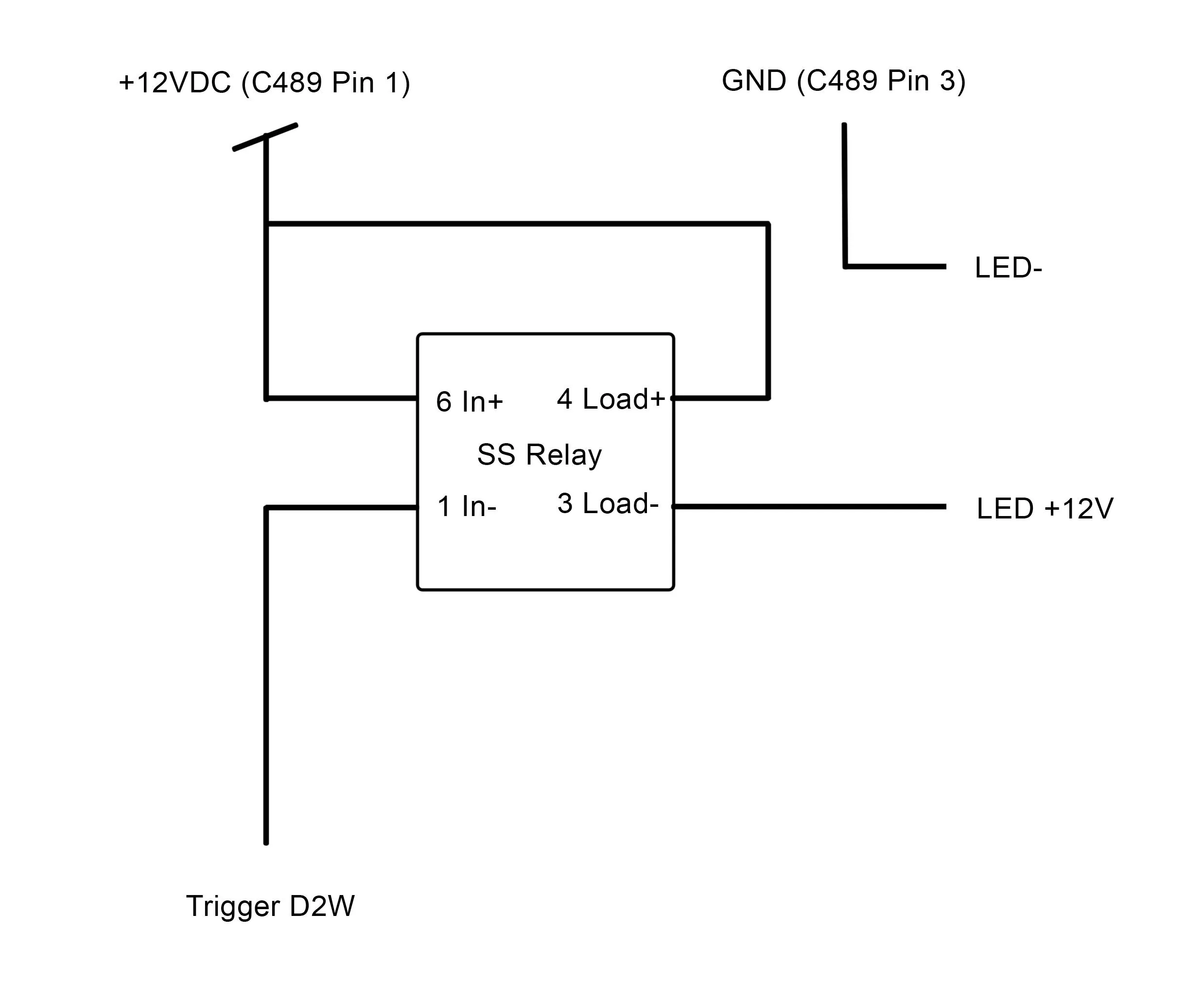
Here is the schematic of the very simple circuit used to drive the LED Strips:

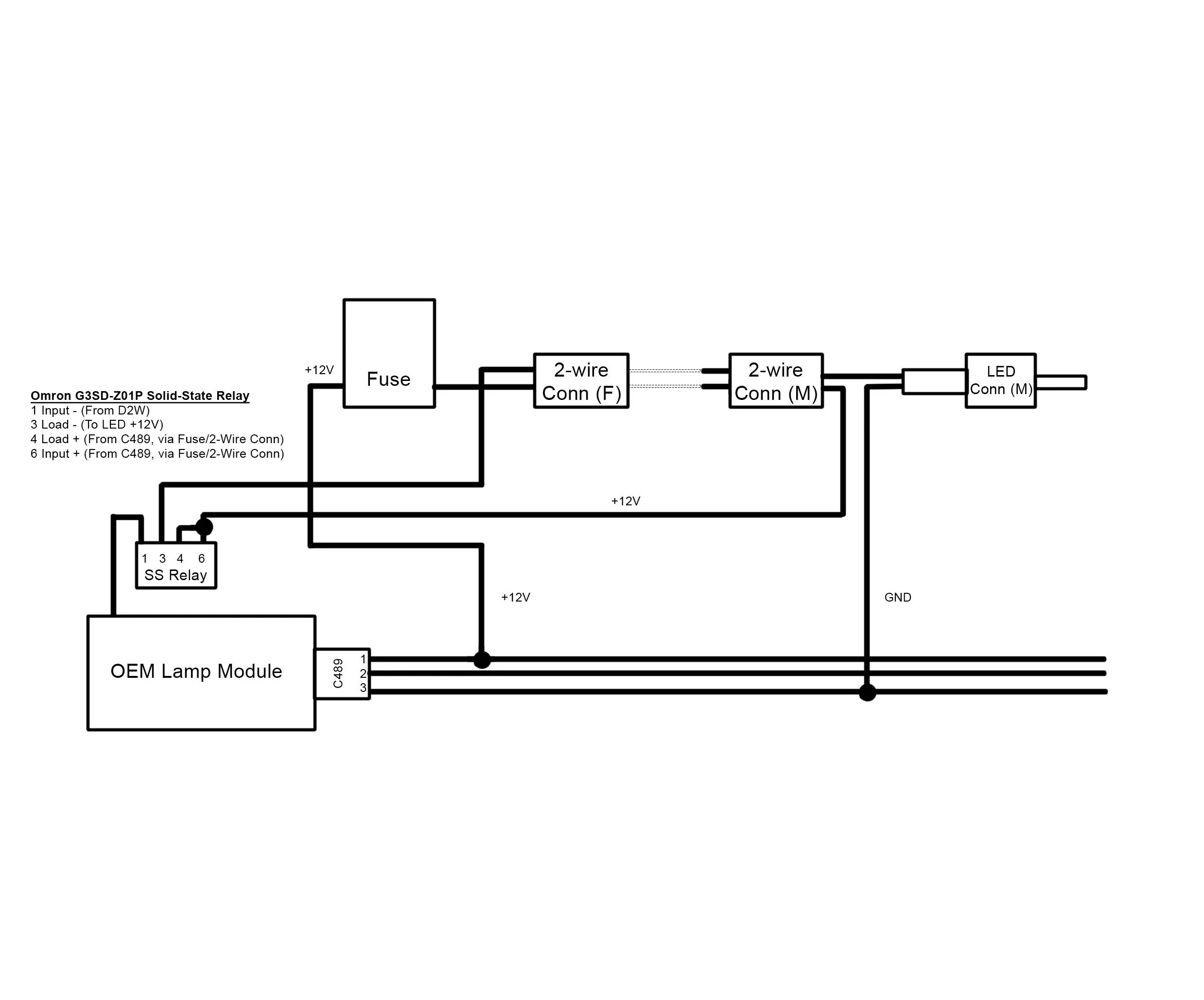
And here is the wiring diagram that shows schematically how I chose to wire up the circuit:
Here is the finished wiring harness. I drilled a hole in the back of the housing for the trigger wire to pass through. You can see the wavey trigger wire coming out of the back and going to the relay. I added 3M locking tape (heavy duty Velcro) to the top of the relay to mount to the back of the housing, though I’d not mounted it yet in this photo.
Here’s everything all buttoned up:

I ran the two LED strips in series, with the wire connecting them running behind the soundproofing under the floor (below the lift gate sill trim). The trim is easy to remove: just two bolts on the inside easily visible, two bolts holding the tie-downs, and a few clips.
Here's the finished result:
Am I happy with the results? Yes! Would I do it again? No! Should you do it? You need to decide, but I really don't recommend it.
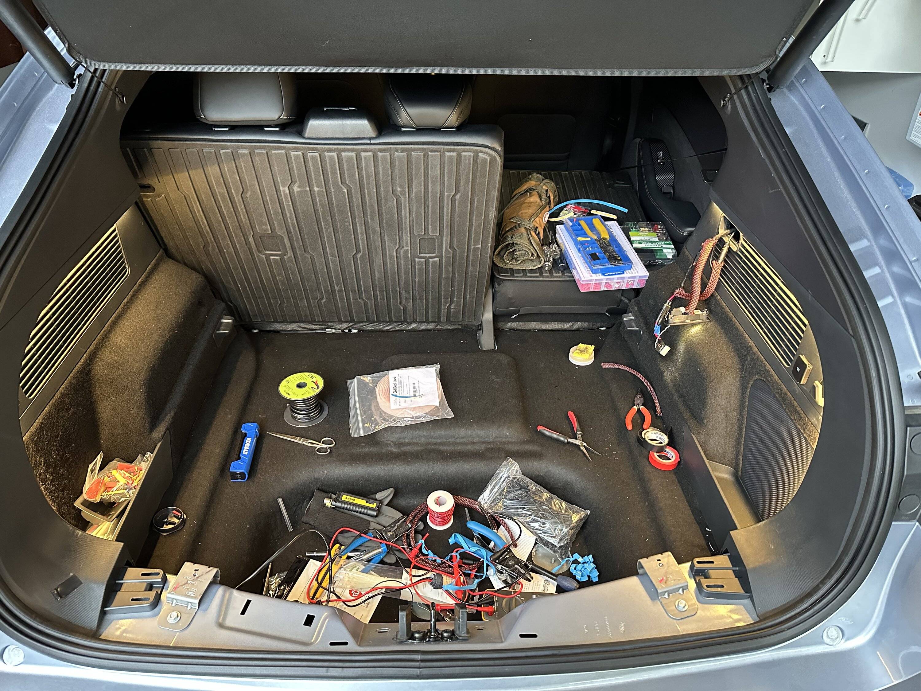
Oh, and here's what my trunk looked like an hour before the video was made:
I decided to see if it is feasible to use the OEM lamp module to trigger a solid-state relay to turn on/off the added LED strips. (My initial idea actually was to try to use the third wire to C489 (Switch – Overhead Console # External Control) to trigger the relay, but I discovered that in fact that wire is the LIN bus to the module and so it cannot be used as a trigger. So I instead needed to do surgery on the OEM lamp module to extract a suitable trigger.
Before we go further, I want to stress that I do not recommend others do this mod! It is time consuming, could easily end up trashing your lamp module, and if things really go south it might even damage your BCM (which would be certifiably bad). If you decide to proceed, you’re on your own. I cannot be responsible for any issues that arise should you attempt this mod.
OK, enough of the backstory and warnings, here’s what I did.
To summarize, we have three input pins on C489 (the connector to the OEM lamp module):
- Battery Saver +12V (this is on whenever the car is on and remains on for about 20 minutes after the car is shut off)
- Switch – Overhead Console # External Control (LIN)
- Ground
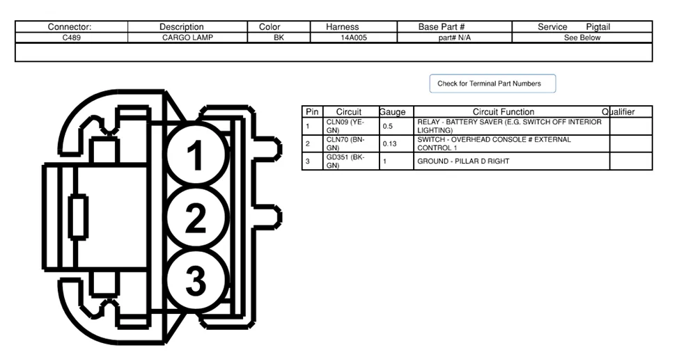
Courtesy @MyLittlePony2022
Pin 2 is the LIN bus and is not used (directly) for this project. Instead, we tap inside the lamp module to obtain the appropriate signal to use with our solid-state relay.
To open the module, you’ll need to remove the clear diffuser plastic by carefully prying it open from behind. There are small tabs that hold it in place and those tabs can be pushed out from behind. Once the diffuser is off, the lens assembly drops out (tapping the module onto its face helps), and then the PCB assembly can be gently pried out. It is simply press-fit in the module housing, so there’s little worry of damaging it if you’re careful.
Here is the disassembled module:
After much testing and basically trashing my lamp module, I determined that Test Point 5 (TP5) is the correct net (signal in a circuit) to drive the SS relay. Tapping that test point directly is not recommended because unless you can protect against all strain to the tap wire, there is a very high probability that you will damage the circuit and need to make repairs (like I did). And while it certainly isn’t for the faint of heart, the best way I could figure out to tap that net is to drill through the PCB. I used a 1/16” drill bit and carefully drilled at the spot shown in the photo below:
I then, on the other side of the PCB, scraped off a small section of the white coating in the area shown below:
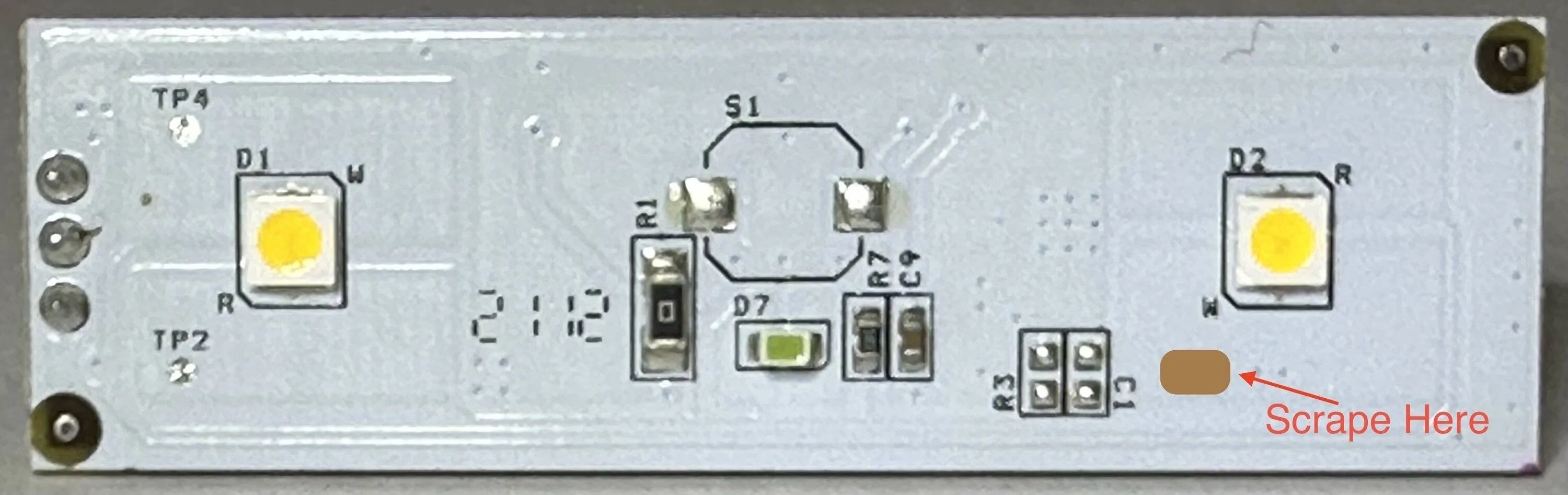
This exposed bare copper which is on the same net as TP5 (and the “W” contact of D2, the yellow colored LED you see on the right side of the PCB shown above).
Below you can see my finished modification. You can run a small wire to the inner pad of the bare C1 spot if you’d like (it is part of the same net).
Do not tap only TP5. I initially did that, and the tap wire pulled up the test point and broke the signal trace. I needed to repair the trace and who knows how long it will last… (Luckily the lamp module isn’t too expensive.)
To switch the LED strips on and off I used a 12VDC Solid-State Relay with a 1-amp load rating (Omron G3SD-Z01P). I purchased it from Digikey.com but unfortunately, I purchased the last one they have in stock, so I don’t know if anyone (crazy enough to try this mod) can easily find it. If you do want to try the mod, I suggest you search for a 12VDC input solid state relay with at least a 1-amp load rating.
Here is the schematic of the very simple circuit used to drive the LED Strips:
And here is the wiring diagram that shows schematically how I chose to wire up the circuit:
Here is the finished wiring harness. I drilled a hole in the back of the housing for the trigger wire to pass through. You can see the wavey trigger wire coming out of the back and going to the relay. I added 3M locking tape (heavy duty Velcro) to the top of the relay to mount to the back of the housing, though I’d not mounted it yet in this photo.

Here’s everything all buttoned up:

I ran the two LED strips in series, with the wire connecting them running behind the soundproofing under the floor (below the lift gate sill trim). The trim is easy to remove: just two bolts on the inside easily visible, two bolts holding the tie-downs, and a few clips.
Here's the finished result:
Am I happy with the results? Yes! Would I do it again? No! Should you do it? You need to decide, but I really don't recommend it.
Oh, and here's what my trunk looked like an hour before the video was made:
Sponsored
") This just makes me think of how cool true ambient lighting would be in this car, and that back seat is just itching for some mod.
This just makes me think of how cool true ambient lighting would be in this car, and that back seat is just itching for some mod.