What charging receptable to install?

mkhuffman

Well-Known Member
First Name
Mike
Joined
Nov 19, 2020
Threads
29
Messages
6,875
Reaction score
9,507
Location
Virginia
Vehicles
2025 Rivian R1T Tri-Max, Jeep GC-L, VW Jetta
Country flag
Actually, in my inderstanding it's the charger inside the car (EV or plug-in) that dictates how much amperage the car will choose to pull on via the EVSE, of whatever type. The OEM car-provided EVSE cord's brick is a communication and safety device only. And the Mach-E pulls a max of about 29 amps on a Level 2 wall or street charging station... likely a notional 32 amps with a little bit of current loss through the charging path. I was just watching a street-side public charging station in Bethany Beach Delaware display this info while my Mach-E was "drinking". So, a 50-amp house circuit for this car is plen-tee as the car cannot exceed 32 amps on any EVSE. My old Fusion could not exceed 16 amps... my even older Prius Gen III could not exceed 12 Amps. My son's Audi E-tron cannot exceed 40 amps. He runs a 14-50 NEMA plug at 50 amps for his OEM car EVSE charging system. Hope this is useful info.
Not sure who told you that, but it’s not correct. Mine pulls 48A all the time.
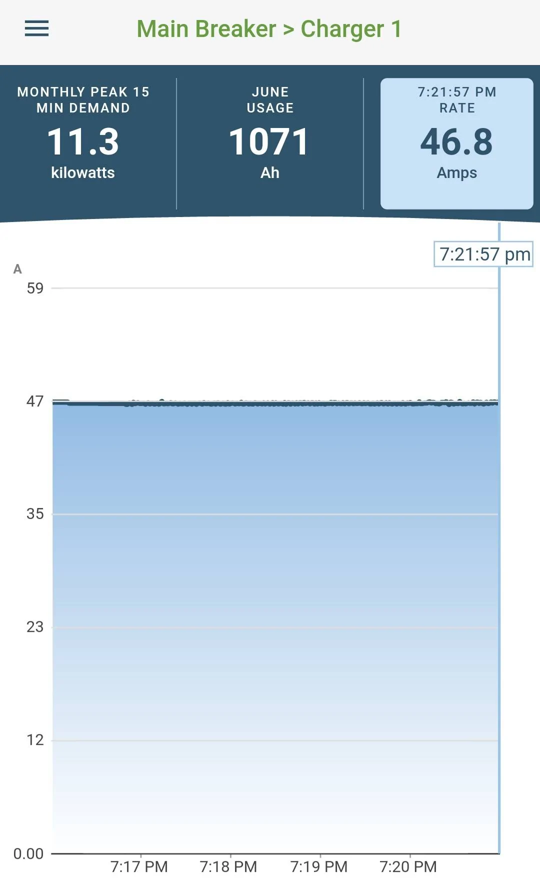
I also have a 48 Amp charger and it also pulls 48 Amps all the time and every time I connect it to my car. Actually, to be more precise, 46.8 Amps and I am charging right now:

Ford Mustang Mach-E What charging receptable to install? 20220618_192241
Sponsored


21st Century Pony

Well-Known Member
First Name
Martin
Joined
May 21, 2022
Threads
36
Messages
1,976
Reaction score
2,243
Location
Arlington, Virginia
Vehicles
formerly Ford Mustang Mach E 2022 Premium AWD ER, now a li'l bit of Lightning ER
Country flag
Not sure who told you that, but it’s not correct. Mine pulls 48A all the time.
I saw the figures on the sidewalk Level 2 charging station's screen. Of course, that charging station could be limited to a max power of 28.8 amps that it was displaying once the charge amperage had stabilized after 2+minutes of starting.
 

devmach-e

Well-Known Member
First Name
David
Joined
Sep 8, 2021
Threads
1
Messages
2,022
Reaction score
2,476
Location
SF Bay Area
Vehicles
2022 Premium RWD ER, 2016 Toyota Highlander Hybrid
Occupation
Unix Sysadmin
Country flag
Article 210.20. Covers overcurrent protection. Continuous load is calculated at 125%. My Grizzle Charger will do 48 amps. That's a 60 breaker. But there are losses in the charger. So it draws 50 amps at max to make 48. Which calculates at 62.5 A. No such breaker and the closest is 70. So I just cut the charger back for a 50 for now. Next one I install I'll do a 60. Waiting on my second EV now.
Your Grizzl-E is not a charger. The charger is actually inside the car. The Grizzl-E is an EVSE (Electric Vehicle Service Equipment). All it does is tell the car the maximum number of Amps that the car can safely draw from the wall, plus employs some safety measures so that power only flows when it is safe to do so, and only when it supposed to. If you are measuring 50A of draw, then there is something wrong with the EVSE.
 

mkhuffman

Well-Known Member
First Name
Mike
Joined
Nov 19, 2020
Threads
29
Messages
6,875
Reaction score
9,507
Location
Virginia
Vehicles
2025 Rivian R1T Tri-Max, Jeep GC-L, VW Jetta
Country flag
Your Grizzl-E is not a charger. The charger is actually inside the car. The Grizzl-E is an EVSE (Electric Vehicle Service Equipment). All it does is tell the car the maximum number of Amps that the car can safely draw from the wall, plus employs some safety measures so that power only flows when it is safe to do so, and only when it supposed to. If you are measuring 50A of draw, then there is something wrong with the EVSE.
You are correct and I agree, but I just want to point out that many people use the word "charger" when referring to EVSEs, including experienced EV people. While technically incorrect, the terms are used interchangeably.

The MME built in charger is a 11 kW charger, so no matter what the EVSE can supply, like the 80 Amp one for the Lightening, it can only charge the car at 11 kW max. 11,000 / 240 = 45.8 Amps. The current the EVSE supplies will be more than the battery accepts because of losses in the system, typically 10%.

https://evgoforth.com/best-home-chargers-for-ford-mustang-mach-e/


generaltso

Well-Known Member
Joined
Jun 24, 2020
Threads
76
Messages
15,389
Reaction score
28,694
Location
Vermont
Vehicles
2024 Kia EV9 GT-Line
Country flag
I saw the figures on the sidewalk Level 2 charging station's screen. Of course, that charging station could be limited to a max power of 28.8 amps that it was displaying once the charge amperage had stabilized after 2+minutes of starting.
Yeah, you were hitting the limit of the EVSE, not the car.
 

Triggerhappy007

Well-Known Member
Joined
Feb 20, 2021
Threads
10
Messages
901
Reaction score
814
Location
TX
Vehicles
23 Premium, 3rd Mach-E
Country flag
I saw the figures on the sidewalk Level 2 charging station's screen. Of course, that charging station could be limited to a max power of 28.8 amps that it was displaying once the charge amperage had stabilized after 2+minutes of starting.
You need to edit or even delete your first post since it has incorrect information. The Mach-E and Audi e-tron can charge up to 48 Amps.
 

devmach-e

Well-Known Member
First Name
David
Joined
Sep 8, 2021
Threads
1
Messages
2,022
Reaction score
2,476
Location
SF Bay Area
Vehicles
2022 Premium RWD ER, 2016 Toyota Highlander Hybrid
Occupation
Unix Sysadmin
Country flag
You are correct and I agree, but I just want to point out that many people use the word "charger" when referring to EVSEs, including experienced EV people. While technically incorrect, the terms are used interchangeably.

The MME built in charger is a 11 kW charger, so no matter what the EVSE can supply, like the 80 Amp one for the Lightening, it can only charge the car at 11 kW max. 11,000 / 240 = 45.8 Amps. The current the EVSE supplies will be more than the battery accepts because of losses in the system, typically 10%.

https://evgoforth.com/best-home-chargers-for-ford-mustang-mach-e/
The internal charger of the Mach-E is rated at 48A @ 240V, which is 11.52 kW. It even says so on Ford’s website. If your feed from the street is higher than 240V, the car will throttle back the amps it is pulling to stay within that 11.52 kW limit.
 

RWG

Well-Known Member
First Name
Randal
Joined
Jan 16, 2022
Threads
0
Messages
169
Reaction score
231
Location
Chaska Minnesota
Vehicles
2021 Mach E
Occupation
Retired
Country flag
See attached document regarding my EVSE set up. This works just fine, so far. After 6 months and dozens of charge sessions. 40 AMP max charge rate is adequate. I did experience a problem with a defective 1450 plug that was overheating and I replace it.

You can set up a system to charge at a higher rate but at the moment I think that is ill advised until the current HVBJB recall is completed and the reason for the contactor overheating/meltdowns is totally understood and resolved.

It occurs to me that a charging session, at 40 amps, for a few hours, puts more continuous power through the HVBJB than any other operating period for this vehicle. I calculate driving @ 3 miles per KW is barely 10 amps of continuous load. A L2 charging session can be easily over 30/40 amps, for hours, and that can generate excessive heat at compromised connections.

Until the HVBJB issue is resolved, we will not be using any EVSE charging system that delivers more than 40 amps. Just to be on the safe side . . . . :cool:

View attachment Mach E charger.pdf
 

mkhuffman

Well-Known Member
First Name
Mike
Joined
Nov 19, 2020
Threads
29
Messages
6,875
Reaction score
9,507
Location
Virginia
Vehicles
2025 Rivian R1T Tri-Max, Jeep GC-L, VW Jetta
Country flag
See attached document regarding my EVSE set up. This works just fine, so far. After 6 months and dozens of charge sessions. 40 AMP max charge rate is adequate. I did experience a problem with a defective 1450 plug that was overheating and I replace it.

You can set up a system to charge at a higher rate but at the moment I think that is ill advised until the current HVBJB recall is completed and the reason for the contactor overheating/meltdowns is totally understood and resolved.

It occurs to me that a charging session, at 40 amps, for a few hours, puts more continuous power through the HVBJB than any other operating period for this vehicle. I calculate driving @ 3 miles per KW is barely 10 amps of continuous load. A L2 charging session can be easily over 30/40 amps, for hours, and that can generate excessive heat at compromised connections.

Until the HVBJB issue is resolved, we will not be using any EVSE charging system that delivers more than 40 amps. Just to be on the safe side . . . . :cool:

View attachment Mach E charger.pdf
If doing that makes you less worried, and it isn't inconvenient, that's great. But for anyone else reading this, the information we have as of today does not support your assessment.

If you floor the accelerator, you will pull more current through the battery than just about anything else you can do. There are smart people in this forum who know the exact amout, but it is probably 400-500 Amps, maybe even more. A DCFC at a typical max charge rate of 150 kW using the battery pack's operating voltage of 350V requires a current of 429 Amps.

So I am not sure where you get the idea that L2 charging puts the heaviest load on the car, but it is incorrect. Also I believe L2 charging uses different contractors and not the ones that are getting damaged when they overheat.

Charging at the maximum L2 charge rate of 48 Amps will not contribute to the likelihood of a HVBJB failure.

If you want to reduce the likelihood of HVBJB failure, don't floor the accelerator when the car is hot, like right after a DCFC or a long drive. Other than that, there is nothing you need to do IMO. Just drive and charge as you want and don't worry about it.
 

devmach-e

Well-Known Member
First Name
David
Joined
Sep 8, 2021
Threads
1
Messages
2,022
Reaction score
2,476
Location
SF Bay Area
Vehicles
2022 Premium RWD ER, 2016 Toyota Highlander Hybrid
Occupation
Unix Sysadmin
Country flag
See attached document regarding my EVSE set up. This works just fine, so far. After 6 months and dozens of charge sessions. 40 AMP max charge rate is adequate. I did experience a problem with a defective 1450 plug that was overheating and I replace it.

You can set up a system to charge at a higher rate but at the moment I think that is ill advised until the current HVBJB recall is completed and the reason for the contactor overheating/meltdowns is totally understood and resolved.

It occurs to me that a charging session, at 40 amps, for a few hours, puts more continuous power through the HVBJB than any other operating period for this vehicle. I calculate driving @ 3 miles per KW is barely 10 amps of continuous load. A L2 charging session can be easily over 30/40 amps, for hours, and that can generate excessive heat at compromised connections.

Until the HVBJB issue is resolved, we will not be using any EVSE charging system that delivers more than 40 amps. Just to be on the safe side . . . . :cool:

View attachment Mach E charger.pdf
If you are driving 60 miles an hour, and getting 3 miles per kWh, that implies a draw of 20 kWh from the battery pack, or roughly the car is is pulling 20 kW on average from the battery. Which is way higher than 40A @ 240V (9.6 kW). Restricting L2 charging to 40A won't do much for the car since those contactors are under significant strain during acceleration or braking, more so than under charging on L2.

I wish the IPC had a kW meter like my Bolt EV did. I can replicate the function with CarScanner, but it isn't the same.
 

RWG

Well-Known Member
First Name
Randal
Joined
Jan 16, 2022
Threads
0
Messages
169
Reaction score
231
Location
Chaska Minnesota
Vehicles
2021 Mach E
Occupation
Retired
Country flag
Gentlemen,

I agree with your technical assessments, and admit I may be totally off base, however I would offer these refined thoughts.

Theoretically, when this vehicle is in L2 charging mode, at 40 amps, that is a continuous draw of power that could be cumulatively higher than occasional power demands of "jamming the accelerator". That is where my assumptive comment came from, but I could be wrong and it all may be irrelevant. I am simply offering an opinion and like many of you, I am frustrated that Ford has not offered any detailed information. They have only acknowledged a problem, via a mandated recall, but not explained what or why, at least, not yet.

Where the possibility of irrelevance comes from is I recently saw a post where one of our learned MME Forum colleagues had obtained a patent disclosure diagram allegedly for this vehicle that seemed to imply there was a separate contactor for charging vs. the driving circuits. If so, this would potentially imply charging has maybe nothing to do with the failures, but on the other hand, a patent disclosure document does not necessarily mean a product is built to that patent specification. I know this first hand because I am a named patent holder on several innovations from my previous employer, but those patents are not in general use anymore. Some patents we filled were never put into use. There are many "strategies" to the issuing of patents, some are purely designed to block others, some are used to better the product, sometimes.

I also have made some assumptions, just based on my 50 years of electromechanical device repairs. I have personally worked on repaired, made mistakes on many, many high voltage, high current contactors/relays. I have replaced dozens of contractors that failed because of high heat issues caused by contactor failures. Root cause of a contactor failure can be elusive. Sometimes it is just a bad, poorly designed product, sometimes it is improper installation, sometimes it is a manufacturing fault, sometimes it is other system failures that seemed totally irrelevant to the failed device, until the truth, root cause was determined.

I post my thoughts on this Forum in hopes that others, who are smarter than I, may be inspired to think of possible resolution outside of what I am implying. I also am hoping the Ford Engineering is reading these posts, because they should. They should not and cannot believe they are the only source of truth.

So, enough of the philosophical pontification, back to the problem at hand.

We have a high voltage, high amperage load contactor that is overheating and failing, that is why there is a recall.

Beyond the pure nature of the technical problem, there are corporate politics to consider.
Be advised when a multinational brand succumbs to a recall, they are tantamount, admitting to a fault, problem, mistake, that opens the company to potential future legal liabilities. So by default, all released information is carefully screened to maybe limit future legal complications. This means, information released by Ford is carefully vetted, and therefore may not necessarily be the whole truth/story. And let's be realistic, at this juncture, Ford my not even fully understand the problem, they just know the outcome, cost, PR disaster, and limited failure data.

Regarding the technical side of this problem:

It has been implied there is no pattern. I do not agree with that statement. There is always a pattern, common thread to component or system failures. I would suggest it is just not known, or maybe not understood or revealed yet. ( When solving technical problems, one must consider "random failures" as a pattern. )

Technical comments about electromechanical contactors /relays.

Every contactor I have ever seen will fail at some point. It is the equivalent to a tire. Sooner or later it will wear out. Unlike a tire, that goes flat, or comes apart, which are the typical life cycle failure modes of a tire. A contactor fails in many other ways:

Cumulative contactor points collateral damage:

Everytime the contactor is energized or de-energized the contactor "points" move to either complete or disconnect a circuit. Everytime those events occur there is a spark. That spark is actually a small "plasma arc" manifested by the disruption of the circuit, i.e. the flow of electrons. Everytime it occurs, the spark reacts with atmospheric gases, creating a small quantity of ozone gas, a highly corrosive gas that can degrade metal surfaces, creating a high resistance, heat generating connection, i.e. more collateral damage. As a contractor gets energized and de-energized hundreds or maybe thousands of times, over its lifetime, each event leaves a small amount of "collateral damage" on the points of the contactor. Is this bad? Well maybe yes or maybe no. Contactor points are designed to be "used up" over time, just like a tire. However, things can happen that will shorten it's useful life. All of us know how to tell if a tire is used up. When this happens, we just replace it an life goes on. If you don't replace it, it will eventually fail and then you will be forced to replace it. We all know, that if you run the tire low on air, it will fail prematurely.

For a high voltage/high current contactor, once point deterioration goes beyond a certain point of no return, when the contactor is energized to complete the circuit, the contact points can, some times, create a continuous, sustainable "plasma arc ball" that creates temperatures in the "thousands of degrees" burning, melting everything within close proximity, maybe even welding the points together or perhaps totally melting the entire device. In contrast, when a tire starts going flat, excessive heat builds up in the sidewalls, because of excessive sidewall flexing, which generates heat and subsequent collateral damage to the sidewall materials, and when the temperature reaches critical levels, the tire simply comes apart. There are similarities to these two failures, collateral damage and excessive heat.

Contactors are designed to spark and live a useful life. So what causes them to fail early?

My experience: I have seen bad connections before or after the contactor circuit, that generated excessive heat that travelled by conduction to the contactor components causing things to melt, fuse, disintegrate. The end result is usually dependant on other external factors.

I have seen situations were the contactor relay coil received inconsistent voltage input from the control system to the point where the contactor points "chattered" because of low voltage to the contactor coil. ( A high voltage/high current contactor that chatters usually fails very quickly, it is equivalent to a welder striking an arc with a welding rod.) Theoretically this could maybe happen if there is a voltage drop during acceleration. Of course, this is pure speculation because I do not know how the operational circuit is designed. Therefore, it is possible, but maybe not probable. There also maybe a software issue where under certain conditions voltage to the contactor coil varies. Again, I do not know. It is possible but maybe not probable.

Another thought. There is the possibility of "spike voltage" plasma arcs causing collateral damage, created when another electrical device in the circuit is de energized. With DC devices, coils, electromagnets, when they are de energized, the collapsing magnetic field can create a significant momentary voltage surge at extremely high voltage. These "spike voltage arcs" can degrade contactor points. Every electrical engineer knows this and there are several ways to prevent the problem. Again, this is a possibility, but perhaps all of the proper design measures were taken, and it is therefore not probable.

These are just a few thoughts about failure modes of contactors, based on my experience. Of course I could be totally wrong. Time will tell. I just want Ford to make the right decisions soon.

All I can do now is wait, hope and take preventive steps.

PS: I must admit, my confidence in Ford has been shaken. The product launch of the "MME laptop on wheels" has been a challenge and the customer experience has not been stellar. All of the fault possibilities I listed should be routine realities presumably taken into design consideration, but where they?

So I am cautious .

I predict the true root cause for this problem may likely come from this forum or some other group, long before Ford takes a public position.

We shall see . . . .
 

mkhuffman

Well-Known Member
First Name
Mike
Joined
Nov 19, 2020
Threads
29
Messages
6,875
Reaction score
9,507
Location
Virginia
Vehicles
2025 Rivian R1T Tri-Max, Jeep GC-L, VW Jetta
Country flag
Gentlemen,

I agree with your technical assessments, and admit I may be totally off base, however I would offer these refined thoughts.

Theoretically, when this vehicle is in L2 charging mode, at 40 amps, that is a continuous draw of power that could be cumulatively higher than occasional power demands of "jamming the accelerator". That is where my assumptive comment came from, but I could be wrong and it all may be irrelevant. I am simply offering an opinion and like many of you, I am frustrated that Ford has not offered any detailed information. They have only acknowledged a problem, via a mandated recall, but not explained what or why, at least, not yet.

Where the possibility of irrelevance comes from is I recently saw a post where one of our learned MME Forum colleagues had obtained a patent disclosure diagram allegedly for this vehicle that seemed to imply there was a separate contactor for charging vs. the driving circuits. If so, this would potentially imply charging has maybe nothing to do with the failures, but on the other hand, a patent disclosure document does not necessarily mean a product is built to that patent specification. I know this first hand because I am a named patent holder on several innovations from my previous employer, but those patents are not in general use anymore. Some patents we filled were never put into use. There are many "strategies" to the issuing of patents, some are purely designed to block others, some are used to better the product, sometimes.

I also have made some assumptions, just based on my 50 years of electromechanical device repairs. I have personally worked on repaired, made mistakes on many, many high voltage, high current contactors/relays. I have replaced dozens of contractors that failed because of high heat issues caused by contactor failures. Root cause of a contactor failure can be elusive. Sometimes it is just a bad, poorly designed product, sometimes it is improper installation, sometimes it is a manufacturing fault, sometimes it is other system failures that seemed totally irrelevant to the failed device, until the truth, root cause was determined.

I post my thoughts on this Forum in hopes that others, who are smarter than I, may be inspired to think of possible resolution outside of what I am implying. I also am hoping the Ford Engineering is reading these posts, because they should. They should not and cannot believe they are the only source of truth.

So, enough of the philosophical pontification, back to the problem at hand.

We have a high voltage, high amperage load contactor that is overheating and failing, that is why there is a recall.

Beyond the pure nature of the technical problem, there are corporate politics to consider.
Be advised when a multinational brand succumbs to a recall, they are tantamount, admitting to a fault, problem, mistake, that opens the company to potential future legal liabilities. So by default, all released information is carefully screened to maybe limit future legal complications. This means, information released by Ford is carefully vetted, and therefore may not necessarily be the whole truth/story. And let's be realistic, at this juncture, Ford my not even fully understand the problem, they just know the outcome, cost, PR disaster, and limited failure data.

Regarding the technical side of this problem:

It has been implied there is no pattern. I do not agree with that statement. There is always a pattern, common thread to component or system failures. I would suggest it is just not known, or maybe not understood or revealed yet. ( When solving technical problems, one must consider "random failures" as a pattern. )

Technical comments about electromechanical contactors /relays.

Every contactor I have ever seen will fail at some point. It is the equivalent to a tire. Sooner or later it will wear out. Unlike a tire, that goes flat, or comes apart, which are the typical life cycle failure modes of a tire. A contactor fails in many other ways:

Cumulative contactor points collateral damage:

Everytime the contactor is energized or de-energized the contactor "points" move to either complete or disconnect a circuit. Everytime those events occur there is a spark. That spark is actually a small "plasma arc" manifested by the disruption of the circuit, i.e. the flow of electrons. Everytime it occurs, the spark reacts with atmospheric gases, creating a small quantity of ozone gas, a highly corrosive gas that can degrade metal surfaces, creating a high resistance, heat generating connection, i.e. more collateral damage. As a contractor gets energized and de-energized hundreds or maybe thousands of times, over its lifetime, each event leaves a small amount of "collateral damage" on the points of the contactor. Is this bad? Well maybe yes or maybe no. Contactor points are designed to be "used up" over time, just like a tire. However, things can happen that will shorten it's useful life. All of us know how to tell if a tire is used up. When this happens, we just replace it an life goes on. If you don't replace it, it will eventually fail and then you will be forced to replace it. We all know, that if you run the tire low on air, it will fail prematurely.

For a high voltage/high current contactor, once point deterioration goes beyond a certain point of no return, when the contactor is energized to complete the circuit, the contact points can, some times, create a continuous, sustainable "plasma arc ball" that creates temperatures in the "thousands of degrees" burning, melting everything within close proximity, maybe even welding the points together or perhaps totally melting the entire device. In contrast, when a tire starts going flat, excessive heat builds up in the sidewalls, because of excessive sidewall flexing, which generates heat and subsequent collateral damage to the sidewall materials, and when the temperature reaches critical levels, the tire simply comes apart. There are similarities to these two failures, collateral damage and excessive heat.

Contactors are designed to spark and live a useful life. So what causes them to fail early?

My experience: I have seen bad connections before or after the contactor circuit, that generated excessive heat that travelled by conduction to the contactor components causing things to melt, fuse, disintegrate. The end result is usually dependant on other external factors.

I have seen situations were the contactor relay coil received inconsistent voltage input from the control system to the point where the contactor points "chattered" because of low voltage to the contactor coil. ( A high voltage/high current contactor that chatters usually fails very quickly, it is equivalent to a welder striking an arc with a welding rod.) Theoretically this could maybe happen if there is a voltage drop during acceleration. Of course, this is pure speculation because I do not know how the operational circuit is designed. Therefore, it is possible, but maybe not probable. There also maybe a software issue where under certain conditions voltage to the contactor coil varies. Again, I do not know. It is possible but maybe not probable.

Another thought. There is the possibility of "spike voltage" plasma arcs causing collateral damage, created when another electrical device in the circuit is de energized. With DC devices, coils, electromagnets, when they are de energized, the collapsing magnetic field can create a significant momentary voltage surge at extremely high voltage. These "spike voltage arcs" can degrade contactor points. Every electrical engineer knows this and there are several ways to prevent the problem. Again, this is a possibility, but perhaps all of the proper design measures were taken, and it is therefore not probable.

These are just a few thoughts about failure modes of contactors, based on my experience. Of course I could be totally wrong. Time will tell. I just want Ford to make the right decisions soon.

All I can do now is wait, hope and take preventive steps.

PS: I must admit, my confidence in Ford has been shaken. The product launch of the "MME laptop on wheels" has been a challenge and the customer experience has not been stellar. All of the fault possibilities I listed should be routine realities presumably taken into design consideration, but where they?

So I am cautious .

I predict the true root cause for this problem may likely come from this forum or some other group, long before Ford takes a public position.

We shall see . . . .
Good points and observations. The HVBJB discussion appears to be spending out into multiple threads.

Regardless, if you read the multiple threads about the issue, my interpretation is the problem is caused by high current which is typically either a DCFC or multiple WOT events. Probably WOT is worse than DCFC as far as contactor load goes, so limiting those when the car is hot makes sense. Limiting L2 charging does not make sense.
Sponsored


Top