louibluey
Well-Known Member
- First Name
- Joe
- Joined
- Dec 21, 2020
- Threads
- 60
- Messages
- 888
- Reaction score
- 1,127
- Location
- NY
- Vehicles
- FE "Louibluey" GB
- Occupation
- retired
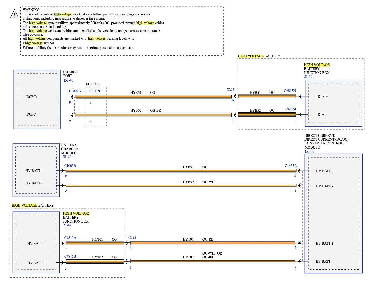
Interesting, I do not completely understand it yet, but this diagram seems consistent with what you are saying. There do appear to be two separate paths to power the DC/DC converter (the bottom two, the top is DC fast charge).See my post above. I believe Energy Transfer System is different than the LVB charging circuit.
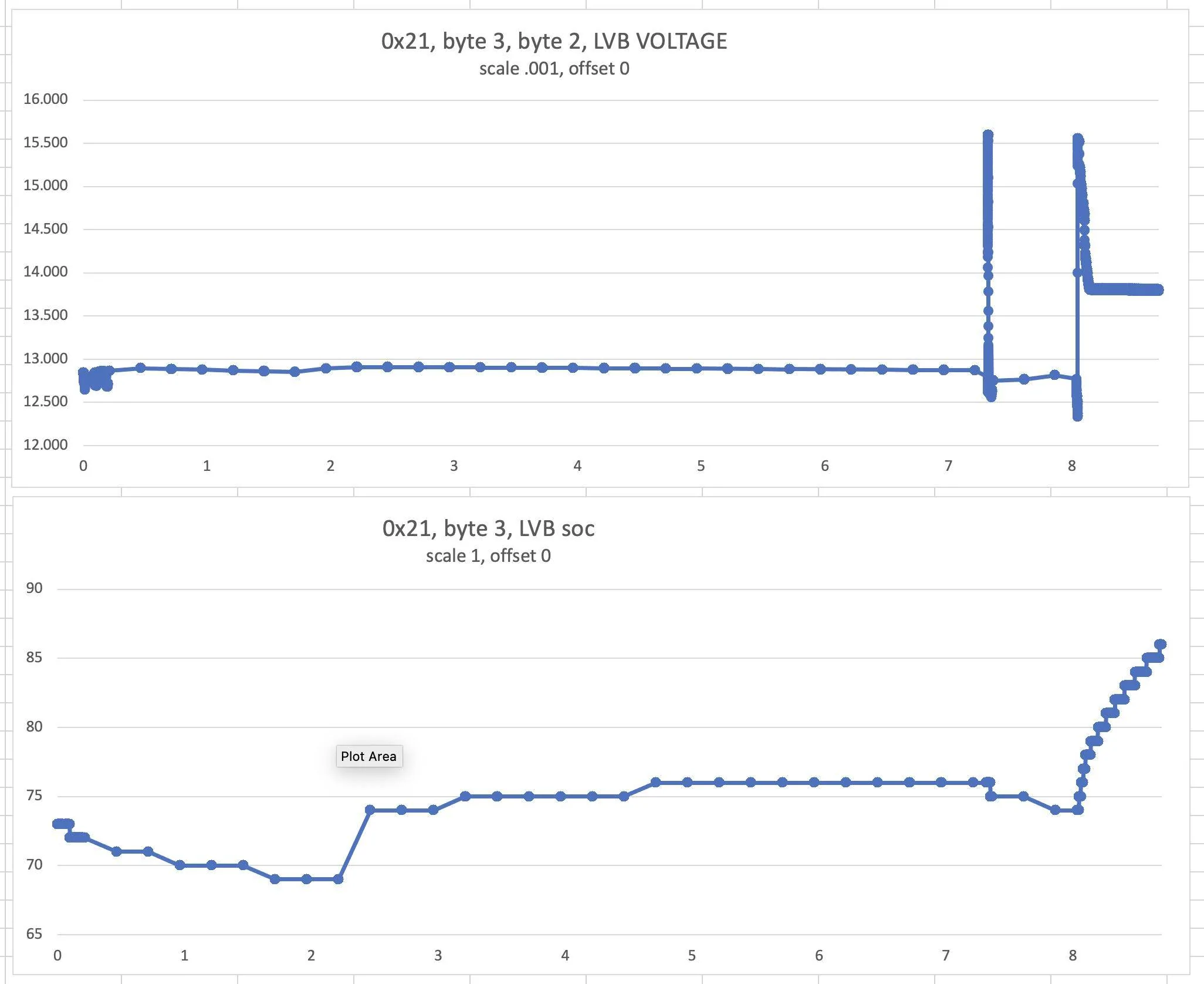
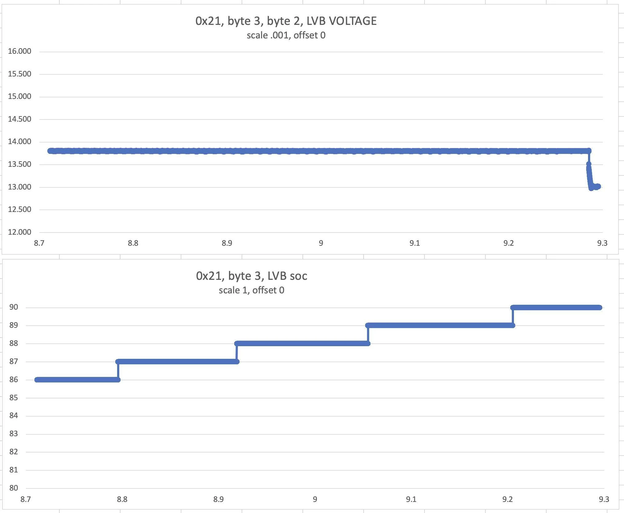
The ETS is for when the car is left parked unattended for a period of time while the LVB Charging System is for normal day to day use.
An auxiliary high voltage cable connects the high voltage battery to each of the high voltage components: cabin coolant heater, ACCM, DCDC and Battery Charger Control Module (BCCM) also known as the SOBDM. Two circuits supply high voltage to the DCDC and two separate circuits supply high voltage to the cabin coolant heater.
It might be more like, one is run from the charger (L1, L2), the charge port, the other while driving, possibly including, not driving, auxiliary and "power on", when not plugged in.
It looks like the battery charger is only active/alive when plugged in (the J1772 plug). That does not mean LVB charges while plugged in, rather, LVB can charge according to the rules, from the HV output of the charger when plugged in L1/L2 (DCFC is different).
@SnBGC, reminds of when were looking at frunk release diagrams together in the "old days".
Sponsored
Last edited:

")