FDRS Battery Error..?

generaltso

Well-Known Member
Joined
Jun 24, 2020
Threads
69
Messages
14,858
Reaction score
27,162
Location
Vermont
Vehicles
2021 MME Premium AWD SR Infinite Blue
Country flag
K, same error came up, but will just continue this time. Wish me luck...

Thanks!
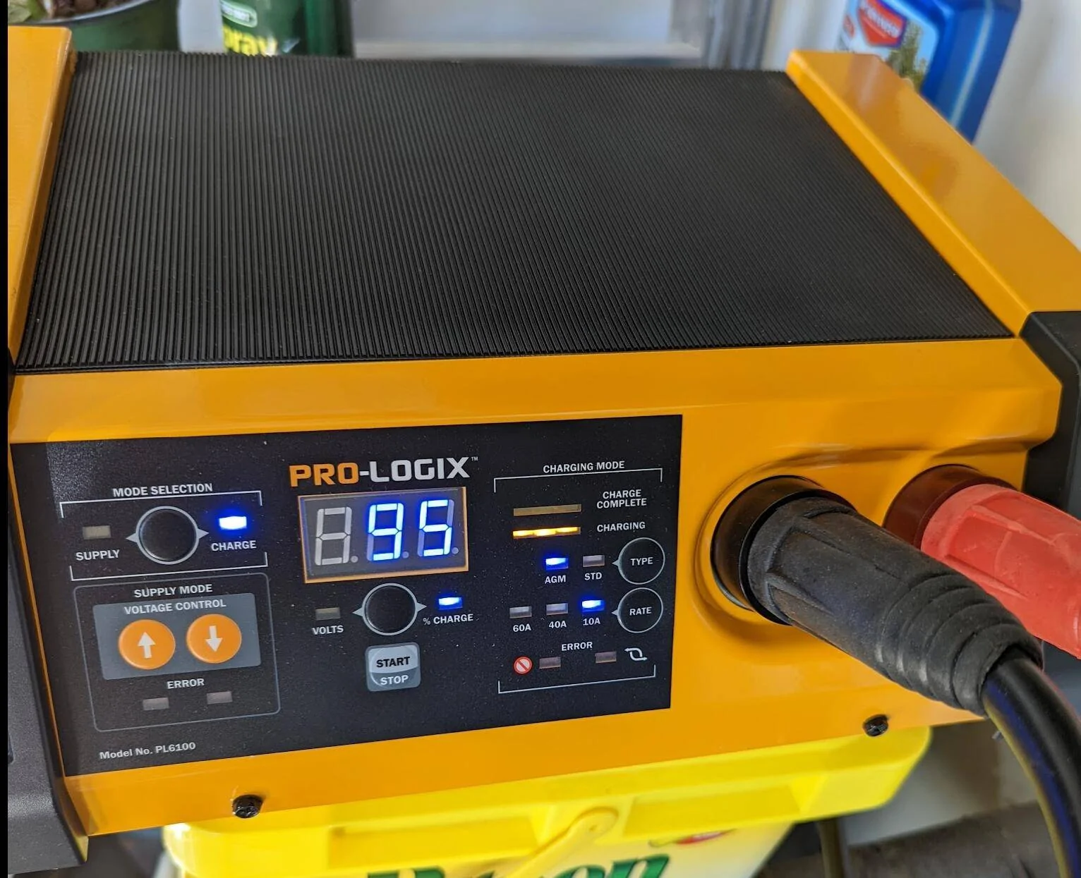
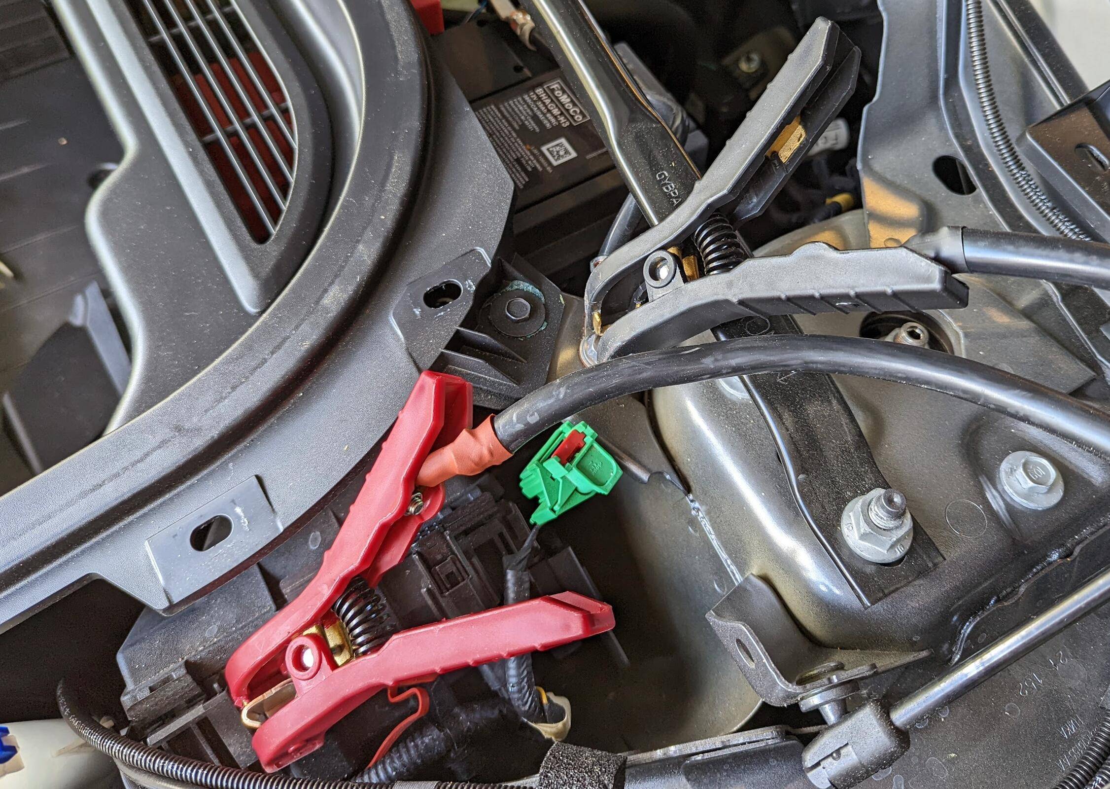
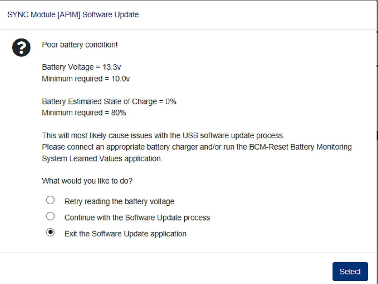
I would expect that, since the car doesn't know that you've been putting power into the LVB for the past few hours. I bet if you leave the power supply hooked up the way it is now for a while, the reported LVB SOC will come back up.
Sponsored


generaltso

Well-Known Member
Joined
Jun 24, 2020
Threads
69
Messages
14,858
Reaction score
27,162
Location
Vermont
Vehicles
2021 MME Premium AWD SR Infinite Blue
Country flag
I don't have FDRS so I don't know.....
Doesn't it link the user to the section in the WSM that shows where to connect the maintainer? For example, when it says to connect the device to the LVB, isn't there a blue hyperlink to the diagram that shows those connections?
No, FDRS doesn't provide any access to the WSM, so the most it does is display possible TSB numbers that match what you're trying to do. But without a PTS account, you can't really do much with that. I really wish FDRS, PTS, and Oasis were all combined into one application. It would make this whole DIY thing much easier.
 

bshaw

Well-Known Member
Joined
May 18, 2020
Threads
12
Messages
1,317
Reaction score
1,799
Location
Boston, MA
Vehicles
2021 Mustang Mach E 4X (Job 1)
Country flag
Assume this is correct now..?

negative-post.png
Cut the access holes so you don’t have to take the panels off to reach the power points next time.

I was able to carefully cut my holes without taking the panels off even once. Follow the excellent diagrams provided on the other thread.
 

SnBGC

Well-Known Member
First Name
Greg
Joined
Apr 20, 2020
Threads
46
Messages
5,958
Reaction score
9,755
Location
Phoenix
Vehicles
2021 Mach-E FE, 2021 Wrangler 4xe High Altitude
Occupation
Manager
Country flag
No, FDRS doesn't provide any access to the WSM, so the most it does is display possible TSB numbers that match what you're trying to do. But without a PTS account, you can't really do much with that. I really wish FDRS, PTS, and Oasis were all combined into one application. It would make this whole DIY thing much easier.
Bummer.
Yeah, you really do need that other stuff. If I could get the PC/ED manual then I would happily pay for it as well.
 

HuntingPudel

Well-Known Member
First Name
Steve
Joined
Mar 23, 2021
Threads
66
Messages
8,312
Reaction score
9,995
Location
Bay Area, CA
Vehicles
2021 MME GT-PE, 1979 Fire-Am, 1972 K/5 Blazer
Occupation
Engineering
Country flag
Cut the access holes so you don’t have to take the panels off to reach the power points next time.

I was able to carefully cut my holes without taking the panels off even once. Follow the excellent diagrams provided on the other thread.
Or do this:

C532CBDE-A889-48F6-B9CB-503F32741EFE.jpeg


louibluey

Well-Known Member
First Name
Joe
Joined
Dec 21, 2020
Threads
60
Messages
888
Reaction score
1,097
Location
NY
Vehicles
FE "Louibluey" GB
Occupation
retired
Country flag
So I decided to take the plunge and bought everything needed to do updates myself. Things have been going smoothly and was able to get myself unstuck from 1.7.1 OTA. I then continued onto the next module APIM/Sync and after 1.5 hrs this error came up. The battery has never gone below the 13.4 while on the battery supply. My HVB is at 69% and I do not have that plugged in as I didn't think it would need to be. Do I need to get above the 80% charge?

Or is this just a warning, and I can just continue since I have everything setup and battery never drops below...?

Thanks,

Ken~

Screenshot 2022-05-14 105314.png
I have a new view on this error. But, first in this specifice case - it was probably caused by the incorrect ground connection, so see if you get this error again with the correct negative post connection, that others have explained.

The following is from the revised 21G01 procedure posted May 4, 2022 Added updated technical info instruction sheet 21G01 by @benk016.

However, for those who get this type of error with the proper jump point connections, I would perform this simple revised Ford procedure first (no matter how big your power supply is) before proceeding with your FDRS programming session:

1. Check the vehicle’s State Of Charge Parameter Identification Data (PID) by performing the following:
• Launch the Ford Diagnostic and Repair System (FDRS) and navigate to toolbox tab > datalogger > BCM and select BATT SOC PID.

• Ensure that the BATT_SOC PID reads over 80%. If the PID is less than 80%, fully recharge the vehicle's 12-volt battery using the appropriate Rotunda battery tester and charger.

• Remove the charger from the vehicle and using FDRS, navigate to toolbox tab > BCM > Reset Battery.

• Monitor Sensor Learned Values application. Perform the BMS reset.
• Connect the Rotunda battery tester and charger and set it to maintain 12.6 to 13.6 volts.Monitor

the voltage real time using the indicator at the bottom right corner of FDRS to ensure that it is within this range.

NOTE: Verify that the negative cable of the charger is installed on a chassis or engine ground, and not the 12 volt battery negative terminal to prevent the battery saver mode from activating on the vehicle.

Ford Mustang Mach-E FDRS Battery Error..? Screen Shot 2022-05-14 at 2.53.54 PM
 
Last edited:

Mach-Lee

Well-Known Member
First Name
Lee
Joined
Jul 16, 2021
Threads
209
Messages
7,937
Reaction score
15,970
Location
Wisconsin
Vehicles
2022 Mach-E Premium AWD
Occupation
Sci/Eng
Country flag
Do I not have this hooked up correctly..? Been doing updates since 8:30am and the battery supply and FDRS never showed it below 13.4V

Ford Mustang Mach-E FDRS Battery Error..? Screen Shot 2022-05-14 at 2.53.54 PM


Ford Mustang Mach-E FDRS Battery Error..? Screen Shot 2022-05-14 at 2.53.54 PM
Bad hooking up this way, BMS will force load shed and shut down modules because it thinks the battery is dead. That will definitely ruin you day programming. % should come back up slowly after fixing the cables, if not reset the BMS.

I wonder how many dealers made this mistake before the % warning was added to FDRS a few weeks ago…
 

louibluey

Well-Known Member
First Name
Joe
Joined
Dec 21, 2020
Threads
60
Messages
888
Reaction score
1,097
Location
NY
Vehicles
FE "Louibluey" GB
Occupation
retired
Country flag
Bad hooking up this way, BMS will force load shed and shut down modules because it thinks the battery is dead. That will definitely ruin you day programming. % should come back up slowly after fixing the cables, if not reset the BMS.

I wonder how many dealers made this mistake before the % warning was added to FDRS a few weeks ago…
I'm pretty sure a lot of dealers completely avoid this connection error by not connecting anything at all :)
 
Last edited:

Jambler

Member
First Name
Jeff
Joined
May 5, 2022
Threads
0
Messages
19
Reaction score
18
Location
CT
Vehicles
Mach-E Premium AWD STD RANGE, Build 3/21, Gray
Occupation
Web
Country flag
I have a new view on this error. But, first in this specifice case - it was probably caused by the incorrect ground connection, so see if you get this error again with the correct negative post connection, that others have explained.

However, for those who get this type of error with the proper jump point connections, I would perform this simple revised Ford procedure first (no matter how big your power supply is) before proceeding with your FDRS programming session:

1. Check the vehicle’s State Of Charge Parameter Identification Data (PID) by performing the following:
• Launch the Ford Diagnostic and Repair System (FDRS) and navigate to toolbox tab > datalogger > BCM and select BATT SOC PID.

• Ensure that the BATT_SOC PID reads over 80%. If the PID is less than 80%, fully recharge the vehicle's 12-volt battery using the appropriate Rotunda battery tester and charger.

• Remove the charger from the vehicle and using FDRS, navigate to toolbox tab > BCM > Reset Battery.

• Monitor Sensor Learned Values application. Perform the BMS reset.
• Connect the Rotunda battery tester and charger and set it to maintain 12.6 to 13.6 volts.Monitor

the voltage real time using the indicator at the bottom right corner of FDRS to ensure that it is within this range.

NOTE: Verify that the negative cable of the charger is installed on a chassis or engine ground, and not the 12 volt battery negative terminal to prevent the battery saver mode from activating on the vehicle.

Ford Mustang Mach-E FDRS Battery Error..? Screen Shot 2022-05-14 at 2.53.54 PM
I did this and it worked well!
 

HuntingPudel

Well-Known Member
First Name
Steve
Joined
Mar 23, 2021
Threads
66
Messages
8,312
Reaction score
9,995
Location
Bay Area, CA
Vehicles
2021 MME GT-PE, 1979 Fire-Am, 1972 K/5 Blazer
Occupation
Engineering
Country flag
OP
OP

kmusk01

Well-Known Member
First Name
Ken
Joined
Jul 29, 2021
Threads
3
Messages
53
Reaction score
27
Location
Charlotte, NC
Vehicles
Mach-E
Occupation
Network Engineer
Country flag
So I just did the BCM reset and thought it was fixed. Took the car for a short drive to make sure things were still working, came back turned it off and the damn error on the sync screen came back!!!! Why is something that should be so simple so difficult. At this point I just want that error to go away before the better half sees it, if not I may not be alive tomorrow :(
 
OP
OP

kmusk01

Well-Known Member
First Name
Ken
Joined
Jul 29, 2021
Threads
3
Messages
53
Reaction score
27
Location
Charlotte, NC
Vehicles
Mach-E
Occupation
Network Engineer
Country flag
I have had the car on charge for a good solid 3 hrs now. According to my battery charger it says 95% and 14.3volts. FDRS says the same voltage in the lower corner. However I was just alerted via the Android Widget that my LVB is low at 13Volts. How is this possible, do I not have a setting correct on the charger..? How long do I need to keep this thing on a charge?

The odd thing is if I open the car door to wake the car up the battery charger then shows 100% so not sure what to believe anymore. I have stopped running updates or lack there of because of this, so today has been a waste basically. The only good thing that has come out of this is that I am now unstuck from 1.7.1 as that was simple to do.

Half tempted at this point to give up and return everything and pray OTA gets me all the updates, but who knows how long that will take. Been a rough day that is for sure :(

Thanks,

Ken~

battery-percent.png
 

louibluey

Well-Known Member
First Name
Joe
Joined
Dec 21, 2020
Threads
60
Messages
888
Reaction score
1,097
Location
NY
Vehicles
FE "Louibluey" GB
Occupation
retired
Country flag
The initial error was probably just from the wrongly connected negative terminal, not the case where the LVB is low.

>>error on the sync screen came back!!!!
What error are you seeing on Sync?

Turn everything off, then connect the PL6100 in the PS "Supply" mode (not charger mode) set to 13.4V, positive and negative cables to the jump posts. Now if you start FDRS, do you still get the battery error?

There are detailed directions for the latest round of updates, not on FDRS, the order of some of the updates is important to follow. Revised 21G01 procedure posted May 4, 2022 Added updated technical info instruction sheet 21G01 by @benk016.

If you have not done the earlier rounds of updates, I do not know if you should or need to do any of those first? Or, can he just dive into 21G01? Question for the experts.

Should he do the Customer Satisfaction Program 21P22 - Software Calibration Update first, before 21G01, if 21P22 has not been done yet? @Mach-Lee?
Sponsored

 
Last edited:


Top