Down for the count :(

Astraea

Well-Known Member
Joined
Mar 20, 2021
Threads
16
Messages
353
Reaction score
543
Location
NY
Vehicles
MMe Premium AWD ER
Country flag
Minor update!

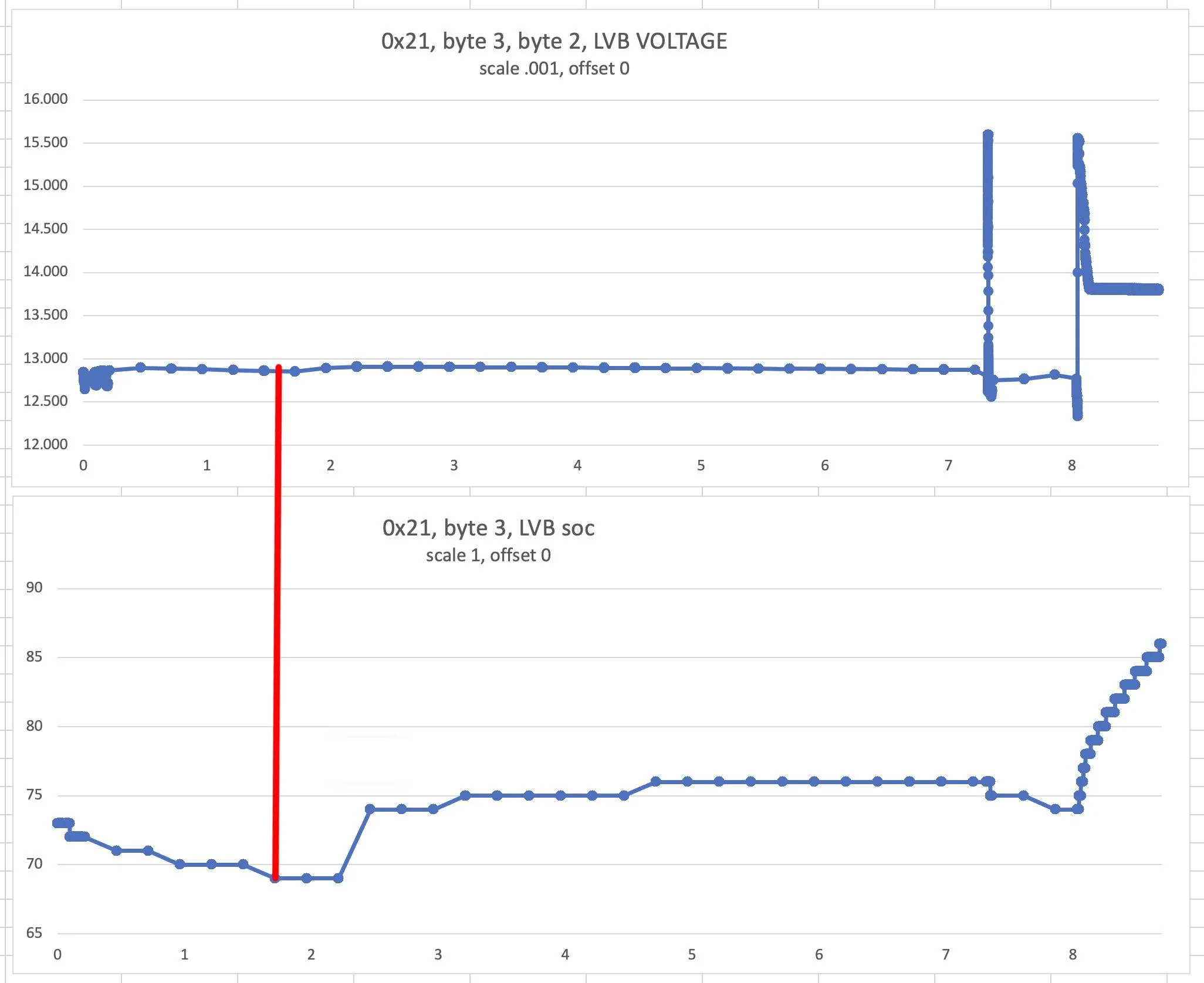
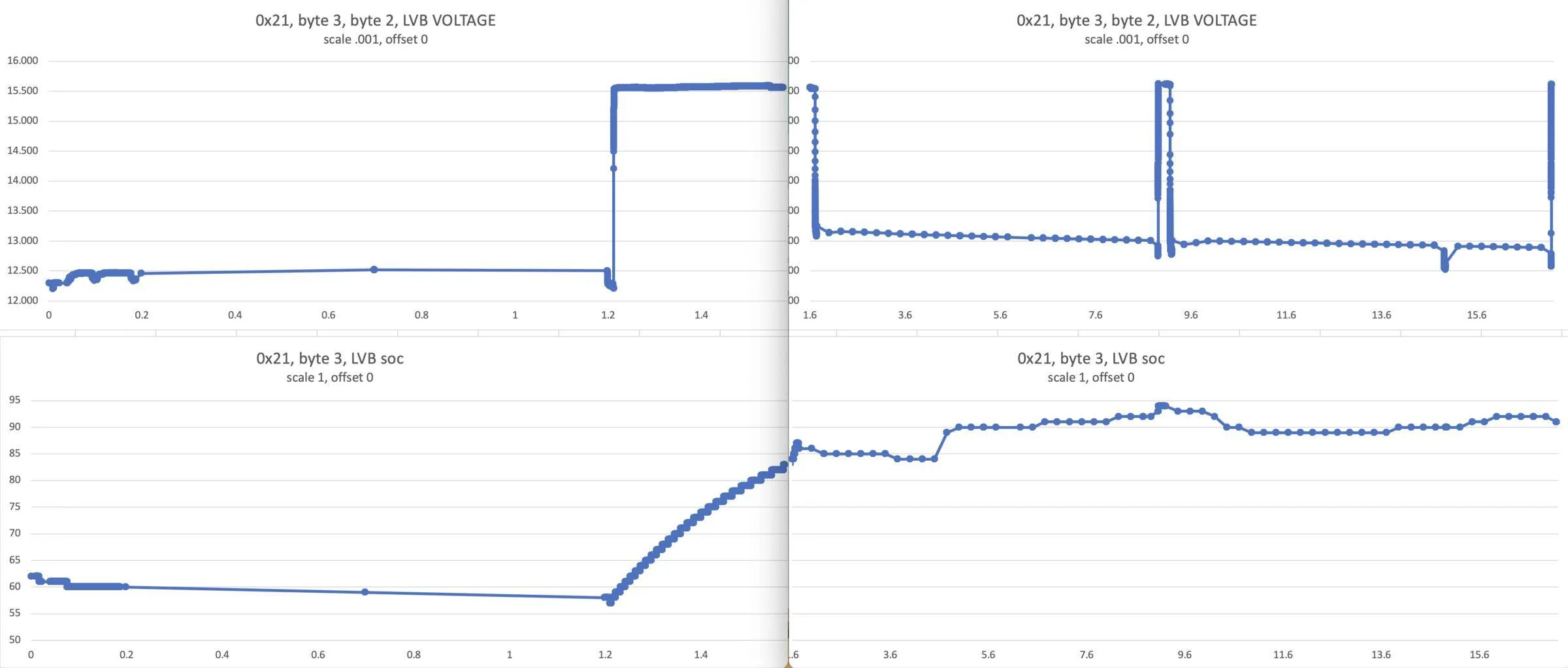
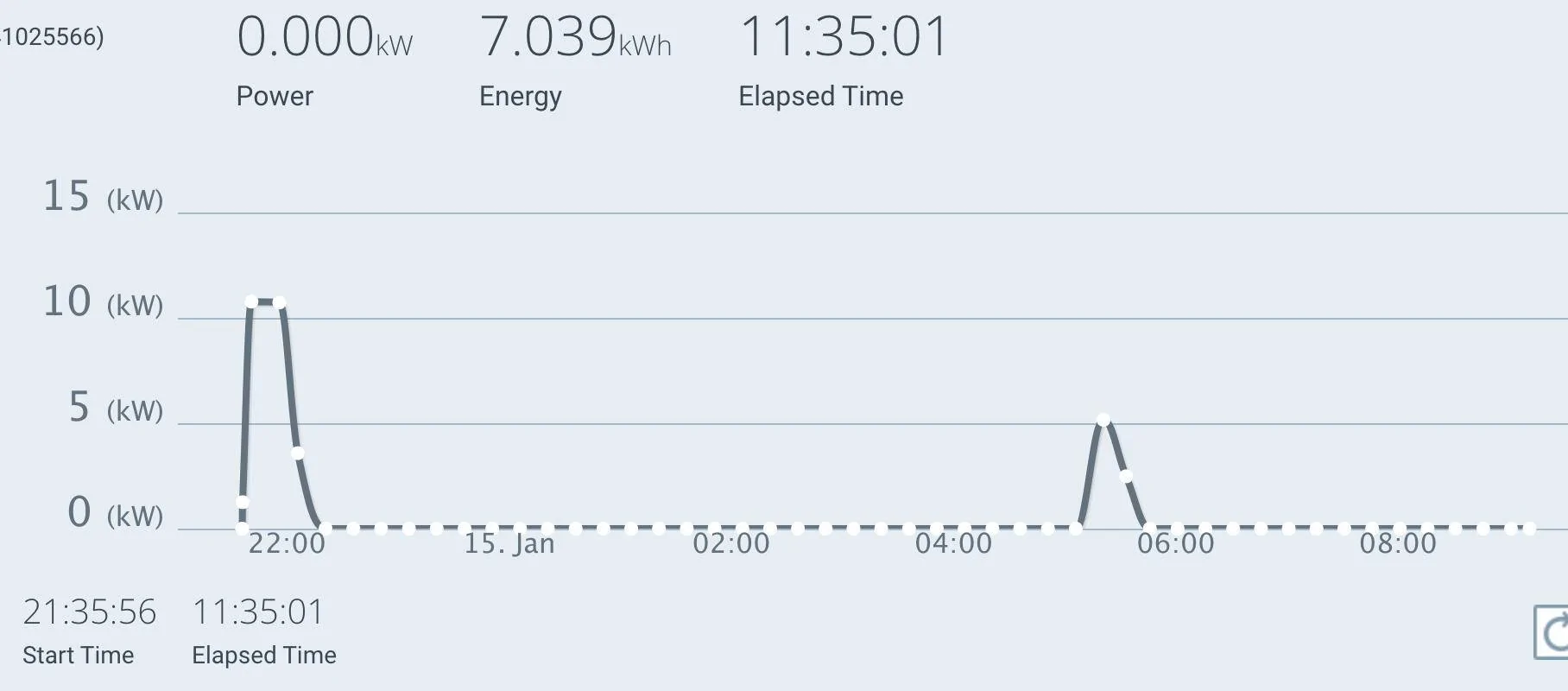
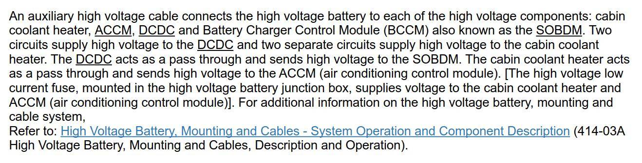
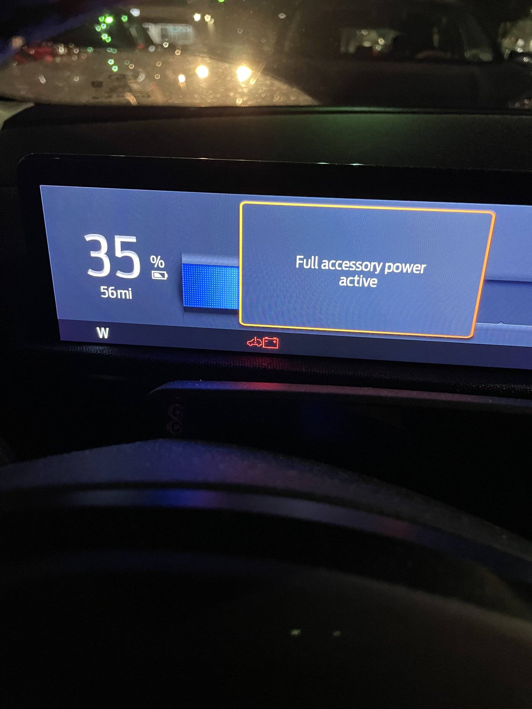
So not to much to report unfortunately, dealership is unable to replicate my or the other MME they have right nows problem. It's supposed to get incredibly cold tonight however, -14F with wind chills nearing -40F ?. So they are going to see how it acts in the morning with the severe cold. I did remember, and told them, that 2 of the 3 times the LVB was dead, I attempted to start the car with the app. To which the app stated the car started and then checking it a minute later didn't show the car as started anymore. ? No idea if this makes a difference or not but mentioned it anyway.
Sponsored


RickMachE

Well-Known Member
Joined
Jul 1, 2021
Threads
200
Messages
13,134
Reaction score
17,851
Location
SE MI
Vehicles
2022 Mach-E Premium 4X, 2022 Lightning Lariat
Country flag
Of course the -14F is all that matters, since wind chill only impacts skin, not cars.
 

dixiekidd88

Well-Known Member
First Name
Joey
Joined
Jan 29, 2021
Threads
11
Messages
296
Reaction score
360
Location
Bay Area, California
Vehicles
21 Prem XAWD, 14 f150 3.5 Ecoboost, 22 Edge ST 2.7
Country flag
Wow I got a call from ford corporate. From what I am told this is the first time for my circumstance. So I’ll post updates when I have them
That is funny because when I forwarded the info I was given on here by @mikeho about the failure part on Wednesday I have got NO RESPONSE from the Ford rep. So I then forwarded the email to the service advisor, glad I did....

Service advisor stated that Ford is AWARE of this concern and the tech has been working with Ford tech assistance rep on it.

Most likely the left hand not knowing what the right is doing because of different Ford reps....as I count now there are about 8 vehicles that I have been able to count between this forum and other resources online.
 

Shayne

Well-Known Member
Joined
Aug 9, 2020
Threads
18
Messages
3,340
Reaction score
2,487
Location
Northern Ontario Canada
Vehicles
2021 MME4x Prem
Occupation
Retired
Country flag
Ford Mustang Mach-E Down for the count :( V-SOC

What is the conclusion did it click on after about 2 hours (no spike?) and slowly charge it to go from 69 to 76% SOC or did the ambient temperature increase over night and nothing much happened because it never reached 40% (sometimes 34%) soc?

Does not seem to charge over about 80% soc at these temps (-16F) lately when on and plugged or not. Not seeing your 90 and trying to not let it go to 40 lately. Departure appears to be somewhat like ON. Came on and ran for 1.5 hours yesterday and it was at 77% at the end; went out and started it and got it up to 79. Maybe I will hook up this reader before departure kicks in. Looking for the easiest way to baby it until service gets back to me. Not really demanding but this 12V problem, like a nonfunctioning charging schedule, I would like to see fixed.

Other than the contactor stuck open message identified by @Shayne, most likely software is the problem. There are probably one or more flaws in the charging strategy that Ford can fix by changes to firmware/software once the problems are better understood.
Do you mean a software fix may not be possible with that confirmed code? What do you think the problem may be? Thinking this is not the first time this has been seen by now.
 

louibluey

Well-Known Member
First Name
Joe
Joined
Dec 21, 2020
Threads
60
Messages
888
Reaction score
1,097
Location
NY
Vehicles
FE "Louibluey" GB
Occupation
retired
Country flag
V-SOC.jpg

What is the conclusion did it click on after about 2 hours (no spike?) and slowly charge it to go from 69 to 76% SOC or did the ambient temperature increase over night and nothing much happened because it never reached 40% (sometimes 34%) soc?

Does not seem to charge over about 80% soc at these temps (-16F) lately when on and plugged or not. Not seeing your 90 and trying to not let it go to 40 lately. Departure appears to be somewhat like ON. Came on and ran for 1.5 hours yesterday and it was at 77% at the end; went out and started it and got it up to 79. Maybe I will hook up this reader before departure kicks in. Looking for the easiest way to baby it until service gets back to me. Not really demanding but this 12V problem, like a nonfunctioning charging schedule, I would like to see fixed.


Do you mean a software fix may not be possible with that confirmed code? What do you think the problem may be? Thinking this is not the first time this has been seen by now.
yes, interesting (your red line above), possibly temperature, maybe also measurement error and uncertainty (that first change in soc with no charging).

Overnight we fell to -10F by morning (garage not heated). Plugged in (L2), MME OFF, Fri Jan 14 08:23:42 PM 2022, ran though early today Jan 15. 1.2 hours in, MME of its own accord, charged the LVB above 85%. The variation in soc after that is a bit of a mystery.

One of my goals last night (did not expect the LVB to charge by itself, but hey, I guess you never know, until we get a better understanding of the rules) was to put the fob in a small stainless steel pot on the other side of the home, and to turn off iPhone. Note that, at least overnight through this am, did not see any of that discharge pattern back down towards 60%. Forgot to turn off iPad and Apple Watch. Usually I keep the fob in the kitchen, close to MME in the attached garage, and iPhone is all over the place during the day.

I think there are several issues, as others have mentioned before, I wonder if some of it is fob, phone motion too close to MME constantly waking MME up and turning lights and other active systems on.

I do think everything short of physically dead/damaged LVB will be fixed by software changes.

odd, MME went to sleep (or "rest" anyway) about 12 minutes in (0.2), then of its own accord (I think), it woke about 1 hour later, 1.2 hours in, and started to charge the LVB for about 0.4 hours (24 minutes, odd I see a 24 minute charging period, almost always at the beginning of testing in auxiliary mode).

Note the change in time scales. The first plot starts Fri Jan 14 08:23:42 PM 2022 and runs for 1.6 hours, the next b plot 15 hours or so. There was no change from the first plot to the second, here I set the LIN monitor to start a new file every 1 MB. When MME is awake data comes in at 25 pts/sec (40 ms), but slows to one point per 15 minutes asleep. Spaced apart dots are 15 minute sleep cycles for perspective. Click on image for a bigger graph.

Ford Mustang Mach-E Down for the count :( Jan 14_15ab


This entire test was plugged in L2, chargepoint rough record overnight. May have topped off the HVB to 80% on that first round.
Ford Mustang Mach-E Down for the count :( Screen Shot 2022-01-15 at 9.16.05 AM
 
Last edited:


SnBGC

Well-Known Member
First Name
Greg
Joined
Apr 20, 2020
Threads
46
Messages
5,955
Reaction score
9,749
Location
Phoenix
Vehicles
2021 Mach-E FE, 2021 Wrangler 4xe High Altitude
Occupation
Manager
Country flag
Interesting, I do not completely understand it yet, but this diagram seems consistent with what you are saying. There do appear to be two separate paths to power the DC/DC converter (the bottom two, the top is DC fast charge).

An auxiliary high voltage cable connects the high voltage battery to each of the high voltage components: cabin coolant heater, ACCM, DCDC and Battery Charger Control Module (BCCM) also known as the SOBDM. Two circuits supply high voltage to the DCDC and two separate circuits supply high voltage to the cabin coolant heater.

It might be more like, one is run from the charger (L1, L2), the charge port, the other while driving, possibly including, not driving, auxiliary and "power on", when not plugged in.

It looks like the battery charger is only active/alive when plugged in (the J1772 plug). That does not mean LVB charges while plugged in, rather, LVB can charge according to the rules, from the HV output of the charger when plugged in L1/L2 (DCFC is different).

@SnBGC, reminds of when were looking at frunk release diagrams together in the "old days".
Ford Mustang Mach-E Down for the count :( Screen Shot 2022-01-15 at 9.16.05 AM
I finally remembered where I saw some text that discusses the wiring. Found it in the 412-00 Climate Control System section of WSM.

Ford Mustang Mach-E Down for the count :( 1642281113987


This helps support the theory about two separate LVB charging methods (Energy Transfer and Charging). I the DCDC is passing HV through to the BCCM directly then that likely is for the energy transfer. There must be a resistor in there to regulate current but could the LVB be exposed to 380v during the Energy Transfer? If so, that would explain the notation in the document provided by @Astraea which said if an energy transfer occurred daily then the LVB would be damaged. I would think so....if that was exposed to HV on a regular basis then it will cook fairly quick.

Interesting....

?
 

cmtaylor963

Well-Known Member
First Name
Charles
Joined
Jun 19, 2020
Threads
4
Messages
239
Reaction score
346
Location
Springfield, MO
Vehicles
Mach E 1st Ed
Occupation
Engineer
Country flag
After updating to 2.3.0 yesterday, I got the Stop Safely Now message and got a tow to the dealership. Throughout the day today, the voltage has steadily dropped and is currently down to 5v while it has sat in their lot.
 

louibluey

Well-Known Member
First Name
Joe
Joined
Dec 21, 2020
Threads
60
Messages
888
Reaction score
1,097
Location
NY
Vehicles
FE "Louibluey" GB
Occupation
retired
Country flag
I finally remembered where I saw some text that discusses the wiring. Found it in the 412-00 Climate Control System section of WSM.

1642281113987.png


This helps support the theory about two separate LVB charging methods (Energy Transfer and Charging). I the DCDC is passing HV through to the BCCM directly then that likely is for the energy transfer. There must be a resistor in there to regulate current but could the LVB be exposed to 380v during the Energy Transfer? If so, that would explain the notation in the document provided by @Astraea which said if an energy transfer occurred daily then the LVB would be damaged. I would think so....if that was exposed to HV on a regular basis then it will cook fairly quick.

Interesting....

?
There is no direct connection between HV and LVB, such as by a resistor.

Only the DC/DC converter can charge the LVB through one path. The only low voltage direct LVB path is from the DC/DC converter to the 12V bus via the heavy cable from the DC/DC converter to the LVB. That same cable is how the DC/DC converter powers everything 12V. When the DC/DC converter is on, the 12 LVB just sits there like a parallel capacitor.

There are at least two HV paths to power the DC/DC converter.

The HV charger which takes AC power from a EVSE plug makes HV to both charge HVB and can power the DC/DC converter, diagram below (middle).

The aux HV cable (and aux hv contactor) is just the way the HVB powers the other HV components, including the DC/DC converter and cabin heat. Diagram below (bottom). I think they wanted to separate it from the main contactor which powers motor drives.

Ford Mustang Mach-E Down for the count :( Screen Shot 2022-01-13 at 8.18.46 PM
 
Last edited:

louibluey

Well-Known Member
First Name
Joe
Joined
Dec 21, 2020
Threads
60
Messages
888
Reaction score
1,097
Location
NY
Vehicles
FE "Louibluey" GB
Occupation
retired
Country flag
I finally remembered where I saw some text that discusses the wiring. Found it in the 412-00 Climate Control System section of WSM.

1642281113987.png


This helps support the theory about two separate LVB charging methods (Energy Transfer and Charging). I the DCDC is passing HV through to the BCCM directly then that likely is for the energy transfer. There must be a resistor in there to regulate current but could the LVB be exposed to 380v during the Energy Transfer? If so, that would explain the notation in the document provided by @Astraea which said if an energy transfer occurred daily then the LVB would be damaged. I would think so....if that was exposed to HV on a regular basis then it will cook fairly quick.

Interesting....

?
There is a high voltage resistor, but it has an entirely different role, just to temper the current in the high voltage distribution system: High Voltage Battery Junction Box - The high voltage battery junction box houses the 6 contactors (precharge, main positive, main negative, auxiliary negative, DC fast charge positive, and DC fast charge negative) which, when commanded closed by the BECM, connects the high voltage battery to various components for high- voltage consumption and/or charging of the high voltage battery. During initial power up after the negative contactors (main negative and auxiliary negative) are closed, the precharge contactor closes prior to the main positive contactor which routes high voltage through the precharge resistor which is also located in the high voltage battery junction box. This reduces the in rush current to prevent contactor damage.

Do we have a diagram of the High Voltage Battery Junction Box? That is interesting, where apparently there are different negative contactors for the motor drives and the aux circuits (DC/DC converter, heater element, etc.), but one common positive contactor for both.

On that note in general, the Police note, I am seriously wondering if it was written by Ford Engineers from the MME electrical designers. For example, that note about lifting the chassis side of the LVB negative terminal is boarder line bizarre. It takes about ten seconds to loosen the 10mm nut and lift the negative terminal. It takes about 10 minutes to get the other side apart. That really makes zero sense to me. Without a clear placard mounted there near the LVB saying what side to lift, there is a ZERO chance that any service people, installers, etc. are going to lift the chassis side of that cable.

This is the HV motor distribution - The high voltage battery junction box design distributes high-voltage via 8 circuits ( RWD) or 10 circuits ( AWD) to various high voltage components. The high voltage battery has four ( RWD or five ( AWD high voltage negative outputs and an equal amount of positive outputs. Two ( RWD) or four ( AWD) high voltage high current circuits supplies the positive and negative polarity to the rear and front (if equipped) Inverter System Controller (ISC). The rear Inverter System controller (ISC) output is protected by a high voltage 630A fuse and the front Inverter System Controller (ISC) (if equipped) is protected by a 150A fuse.

This is the HV DC/DC converter and other HV users distribution - Two high voltage low current circuits supplies the negative and positive polarity to the DCDC and Battery Charger Control Module (BCCM) also known as the SOBDM and is protected by a high voltage 50A fuse. Two additional high voltage low current circuits supplies negative and positive polarity to the Cabin Coolant Heater and ACCM and is protected by an additional high voltage 50A fuse.

Not clearly written, I believe they are referring to the two paths of the diagram above, where low current HV is supplied by the HV battery charger (Wall AC to HV) or where low current HV is supplied by the aux HV cables from the HV battery (as controlled by the separate HV aux negative contactor, where the positive connection is through a common positive contactor.

Honestly, I am starting to question the credibility of that Police note. It takes about 10 seconds to loosen the 10mm nut to lift the negative terminal from the battery. It takes 10 minutes + to undo the chassis side of that cable by removing the negative jump terminal. If it was so critical not to loosen the 10mm side, I would expect a caution note there. Any installer, service tech, guaranteed, is going to lift the BMS side with the 10mm nut.
 
Last edited:

hawkeye3point1

Well-Known Member
Joined
Nov 13, 2021
Threads
0
Messages
481
Reaction score
453
Location
NH
Vehicles
Space White ER RWD, Born on 12 Aug. '21
Country flag
On that note in general, the Police note, I am seriously wondering if it was written by Ford Engineers from the MME electrical designers. For example, that note about lifting the chassis side of the LVB negative terminal is boarder line bizarre.
As someone who writes this kind of modification procedure, I can assure you that these types of instructions are typically dictated by a Mechanical Engineer that has completed a root cause analysis of failures that have occurred in the factory or in the field service environment. If that is the case, a Field Bulletin is usually distributed in advance of some sort of warning/caution markings being added to the product.

Not clearly written, I believe they are referring to the two paths of the diagram above, where low current HV is supplied by the HV battery charger (Wall AC to HV) or where low current HV is supplied by the aux HV cables from the HV battery (as controlled by the separate HV aux negative contactor, where the positive connection is through a common positive contactor.
The charger HV connections to the DCDC has me curious. Do you know how the rectified 240 vac (which would be well below the 350-400 vdc need to charge the HVB is boosted? Is there a transformer in the onboard charger? That seems like a solution that would add a lot of weight. I am wondering if the DCDC takes the DC from the OBC, upconverts and outputs at charge potential when Level 2 charging. Conversely when not charging, that same connection would supply HV to the DCDC to be used for LVB maintenance as needed.
 

SnBGC

Well-Known Member
First Name
Greg
Joined
Apr 20, 2020
Threads
46
Messages
5,955
Reaction score
9,749
Location
Phoenix
Vehicles
2021 Mach-E FE, 2021 Wrangler 4xe High Altitude
Occupation
Manager
Country flag
There is no direct connection between HV and LVB, such as by a resistor.

Only the DC/DC converter can charge the LVB through one path. The only low voltage direct LVB path is from the DC/DC converter to the 12V bus via the heavy cable from the DC/DC converter to the LVB. That same cable is how the DC/DC converter powers everything 12V. When the DC/DC converter is on, the 12 LVB just sits there like a parallel capacitor.

There are at least two HV paths to power the DC/DC converter.

The HV charger which takes AC power from a EVSE plug makes HV to both charge HVB and can power the DC/DC converter, diagram below (middle).

The aux HV cable (and aux hv contactor) is just the way the HVB powers the other HV components, including the DC/DC converter and cabin heat. Diagram below (bottom). I think they wanted to separate it from the main contactor which powers motor drives.

Ford Mustang Mach-E Down for the count :( Screen Shot 2022-01-13 at 8.18.46 PM
Is there a heavy cable connection from the LVB to BCCM?
 

PA Bob

Well-Known Member
First Name
Robert
Joined
Aug 20, 2021
Threads
9
Messages
164
Reaction score
108
Location
PA
Vehicles
Premium RWD SB
Country flag
UPDATE: was told the 12v died. They replaced it but the car still doesn’t shift, move or take a charge. So there are many unknowns right now. I was told that they called the mothership and they will beam down their best people to see what’s going on. Will update when I have more info.

Ford Mustang Mach-E Down for the count :( Screen Shot 2022-01-13 at 8.18.46 PM

Currently waiting for a tow. 28k miles in and now it strands me. Thank the lord it was in a parking lot. Surprised the only pop up I got was “stop safely” the app says the car condition is good though with a green check lol. Hopefully the tow gets here quick cause its 10degrees. :(
Here is a link to a post about reconditioning the 12v battery. I just picked mine up and I'm going to do this pronto.

https://www.macheforum.com/site/threads/how-to-recondition-service-your-12v-battery.11069/
 

mikeho

Well-Known Member
First Name
Mike
Joined
Jun 25, 2020
Threads
10
Messages
158
Reaction score
134
Location
San Jose, CA
Vehicles
Mustang Mach-E
Country flag
There is a high voltage resistor, but it has an entirely different role, just to temper the current in the high voltage distribution system: High Voltage Battery Junction Box - The high voltage battery junction box houses the 6 contactors (precharge, main positive, main negative, auxiliary negative, DC fast charge positive, and DC fast charge negative) which, when commanded closed by the BECM, connects the high voltage battery to various components for high- voltage consumption and/or charging of the high voltage battery. During initial power up after the negative contactors (main negative and auxiliary negative) are closed, the precharge contactor closes prior to the main positive contactor which routes high voltage through the precharge resistor which is also located in the high voltage battery junction box. This reduces the in rush current to prevent contactor damage.

Do we have a diagram of the High Voltage Battery Junction Box? That is interesting, where apparently there are different negative contactors for the motor drives and the aux circuits (DC/DC converter, heater element, etc.), but one common positive contactor for both.
Well, my car got fixed from this issue after replacing the High Voltage Battery Junction Box, so I suppose some of these contactors or the resistor is failing, prevent energy from flowing through the junction box properly.
 

Badger_Prof

Well-Known Member
First Name
Randy
Joined
Jun 22, 2020
Threads
4
Messages
759
Reaction score
1,539
Location
Wisconsin
Vehicles
Prior--Leaf,Bolt EV. Mustang Mach-E Premium AWD ER
Country flag
I am deeply saddened that any of us need to worry about this and trying to come up with ideas to get ahead of it before it becomes a major problem like some of us are having. I kind of hate to say it, but I'm surprised this hasn't hit media yet with how much of a major safety problem this is.
Perhaps it has not hit the media because it is not a common problem. It could be but a few people citing and re-citing it on a forum does not mean it is a common problem. Don't get me wrong, this is a HUGE problem if it happens to you but that does not make it common.
 

Mach-Lee

Well-Known Member
First Name
Lee
Joined
Jul 16, 2021
Threads
203
Messages
7,730
Reaction score
15,305
Location
Wisconsin
Vehicles
2022 Mach-E Premium AWD
Occupation
Sci/Eng
Country flag
OK, I was busy last week so missed all this action. A couple things to add:

The "HV to LV Energy Transfer" simply refers to charging the 12V battery when the car is off because it got too low. It is done the same/usual way with the DC/DC converter powered the same/usual way from the HV battery so it's not a special method or different route of charging. It's a special condition triggered by a 12V battery that has gotten too low, which should be rare. When an energy transfer occurs, you get the FordPass message about battery service. They call it an energy transfer because 300 Wh of energy is transferred, which should add back about 70% charge to the 12V battery. The BMS can measure and keep track of energy transferred (volts and amps), which is the basis of the SoC reading it maintains. Some of you noticed the SoC reading changing even though the battery voltage didn't, this is because of temperature or because the BMS is updating the SoC estimate after measuring the open circuit resting voltage after being parked several hours. This is why "idle time" is important for the BMS to update accurately.

The HV to LV transfers are supposed to be limited so as to not cause excess drains to the HV battery or wear and tear on the 12V battery. This is probably the reason for the 48 hour lockout, to eliminate an unnecessary transfer when the battery could just be charged when you drive it the next day. Also, a transfer won't occur when the HV battery is below 15% (to save the HV battery from dying), I think this is why new cars show up with dead 12V batteries. The Mach-E is supposed to be charged if it gets below 25% during transport so that doesn't happen, but most rail yards don't have EV chargers.

When the car is ON, the battery is maintained with normal charging system voltage.

@louibluey I'm not sure about the specifics of them not wanting you to remove the 10mm sensor end of the (-) battery cable, my guess is they are worried about stress to the fragile sensor causing damage. The other end is much more robust. The service manual includes this specific warning:

NOTICE: Do not remove or install the M8 nut on the cable eyelet bolt while the battery monitor sensor is attached to the battery post as this causes damage to the sensor, connector, and possibly the battery post and case.

It was also explained that the DC/DC uses a separate set of auxiliary contractor, and the AC charger (SOBDM) shares the same wires back to the battery. If there was a problem with those contactors (such as sticking), the 12V battery won't be able to charge, even though the car might still be drivable. I've seen some evidence that the 12V battery becomes discharged after getting a red ring charge fault, but I'm not sure if that's because of software or hardware. We could have a situation in software where the car just forgets to turn on the DC/DC converter when it's supposed to, and lets the 12V battery die rather than charging it.
Sponsored


Top